
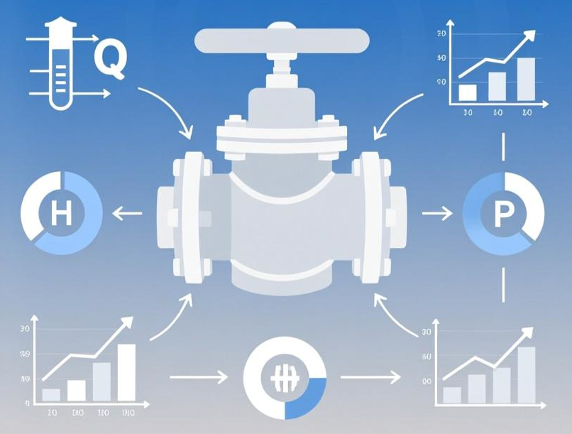
Picking a control valve is really a sequence of decisions, and each one depends on the ones before it. Skip a step and you can end up with a valve that is too small, unstable at the operating point, or unable to shut off when it should. The eight steps below, taken in order, produce a specification you can verify point by point against the duty: service conditions, valve sizing, body type, flow characteristic, actuator, trim materials, leakage class and accessories.
Step 1: Define the Service Conditions
Everything starts with process data. Write down the fluid (name, phase, density, viscosity and corrosiveness), the maximum, normal and minimum flow rates, the inlet and outlet pressures, the operating temperature and the allowable pressure drop across the valve. If these numbers are wrong, nothing downstream of them can be trusted.
Step 2: Size the Valve
Calculate the required flow coefficient from the maximum flow and the allowable pressure drop, then pick a valve whose rated Cv or Kv sits about 30 % above the calculated value. That margin keeps the valve working in its best control range at maximum flow. For the calculation itself and a worked example, see our guide on control valve Kv and Cv values.
Step 3: Choose the Valve Body Type
Body type comes next, and it follows from the duty. A single-seat globe valve is the general-purpose workhorse, with tight shut-off and fine throttling. Double-seat valves give higher capacity and balanced forces but leak more. Cage-guided valves keep the plug guided and make trim replacement easy, which pays off in high-pressure-drop service. Three-way valves mix or divert flows, common in temperature control systems. Angle valves suit high pressure drops, flashing and cavitating service, or cramped piping. Control ball valves, in V-notch and O-type designs, handle on-off duties and viscous, fibrous or slurry media.
Step 4: Select the Flow Characteristic
The flow characteristic should match how the pressure drop behaves across the system. Linear suits constant pressure drop, equal percentage suits varying pressure drop and wide regulation, which makes it the default for most duties, and quick-opening suits on-off service. Our comparison of control valve flow characteristics covers the three curves in detail.
Step 5: Select the Actuator
Work from the energy available and the control requirement. Pneumatic gives fast response, high thrust, intrinsically safe operation and easy spring-return fail-safe. Electric is the choice when there is no instrument air and precision automation matters. Self-operated units run with no external energy at all. The trade-offs are laid out in our actuator selection guide.
Step 6: Select Trim and Seat Materials
Match body and trim materials to the media. Aggressive fluids call for alloy bodies or PTFE lining, high temperature calls for heat-resistant grades, and erosion or cavitation calls for hard facings such as stellite or tungsten carbide. The material selection guide covers the options in full.
Step 7: Define the Leakage Class
Decide how tight the shut-off has to be. Class IV with a metal seat is the standard for throttling valves, Class V covers very tight shut-off at high pressure, and Class VI with a soft seat gives bubble-tight shut-off where the media is clean. Our guide to control valve leakage classes explains the differences.
Step 8: Specify Accessories
Finally, list the accessories: a smart positioner with HART, Foundation Fieldbus or Profibus communication, a handwheel for manual override, limit switches, solenoid valves, filter regulators, and volume boosters where fast response is needed.
Summary Table
| Step | What You Determine | Key Factor |
|---|---|---|
| 1. Service conditions | Fluid, flow rates, pressures, temperature | Accuracy of process data |
| 2. Valve sizing | Required Cv/Kv and nominal diameter | Maximum flow and allowable pressure drop |
| 3. Body type | Single/double seat, cage, three-way, angle, ball | Service, capacity and shut-off requirements |
| 4. Flow characteristic | Linear, equal percentage, quick-opening | Pressure drop behavior of the system |
| 5. Actuator | Pneumatic, electric or self-operated | Energy available, response and fail-safe needs |
| 6. Trim materials | Body, plug and seat materials | Corrosion, temperature and erosion resistance |
| 7. Leakage class | Class IV, V or VI | Shut-off importance and media properties |
| 8. Accessories | Positioner, handwheel, switches, solenoid | Control, automation and safety requirements |
Conclusion
Working through these eight steps gives you a complete specification, and each line of it can be checked against the duty. If the service conditions are unusual, or the sizing result lands close to a size boundary, run the selection past the manufacturer’s engineers before ordering. The calculated size, the duty data and this checklist together form a specification that can be confirmed before the valve is built.
 No products in the cart.