
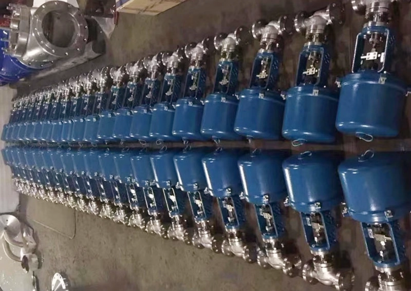
As industrial automation continues to advance, the valve, as the final control element in the process control loop, directly determines the accuracy and reliability of the entire control system. Among the many valve types, the electric single-seat control valve, with its excellent regulation accuracy, stable operating performance and reliable control characteristics, is widely used in key industries such as petrochemical, power and energy, pharmaceutical and food.
This article fully explains the core technical parameters, product advantages, selection points and maintenance methods of the electric single-seat control valve, helping you gain a deeper understanding of this key industrial component.
Product Overview
What is an electric single-seat control valve?
An electric single-seat control valve is a final control element for industrial process control, consisting of an electric actuator and a single-seat control valve body. It receives standard electrical signals from the control system (4-20 mA / 0-10 V), drives the actuator to move the plug up and down, and changes the flow area between the plug and the seat, thereby precisely regulating process parameters such as flow, pressure and temperature in the piping.
The “single-seat” structure means that the valve body has only one seat and one plug in engagement. This construction gives the valve outstanding features: low leakage and good sealing performance.
Basic working principle
- Signal reception: the electric actuator receives standard control signals from DCS, PLC and other control systems.
- Motor drive: the servo motor inside the actuator produces torque according to the signal value.
- Stroke conversion: the rotation of the motor is converted into linear movement of the plug through a reduction gear and a screw.
- Throttling regulation: plug displacement changes the flow area, achieving continuous regulation of the media flow.
- Position feedback: the built-in position sensor feeds the valve position signal back to the control system in real time.
Main application fields
| Industry | Typical Application | Media Examples |
|---|---|---|
| Petrochemical | Reactor feed control; distillation column temperature regulation | Crude oil, chemical feedstock, steam |
| Power and energy | Boiler feedwater regulation; turbine bypass control | High-temperature high-pressure water, superheated steam |
| Pharmaceutical | Fermentation tank temperature control; clean media transfer | Drug solutions, clean steam |
| Food and beverage | Sterilization temperature control; batching ratio regulation | Juice, dairy products, syrup |
| Water treatment | Dosing control; filtration system regulation | Sewage, chemicals, clean water |
Features and Advantages
High-precision control performance
- Regulation accuracy up to ±0.5 % ~ ±1 %, meeting the most stringent process control requirements.
- Rangeability up to 50:1, maintaining stable regulation over a wide flow range.
- Accurate flow characteristic curves; equal percentage, linear and quick-opening characteristics are selectable.
Reliability and stability
- Body material: high-quality stainless steels such as CF8, CF8M and CF3M.
- Plug and seat: specially hardened treatment (Stellite hard-facing, nitriding).
- Packing seal: low-emission packing system effectively reduces external media leakage.
- Service life: under normal operating conditions, key components can last more than 10 years.
Intelligent control functions
- Intelligent electric actuator: supports bus communication (HART, Profibus, FF, Modbus).
- Self-diagnosis: monitors actuator status in real time and provides early warning of potential faults.
- Auto calibration: one-touch stroke calibration and zero/span setting.
- Fail-safe mode: supports hold-last-position, full-open or full-closed on power or signal loss.
Technical Parameters
Basic technical parameters
| Parameter | Typical Range | Notes |
|---|---|---|
| Nominal diameter (DN) | DN15 – DN300 | Selected by pipe size and flow requirements |
| Nominal pressure (PN) | PN16 / PN25 / PN40 / PN64 / PN100 | ANSI 150LB – 600LB |
| Flow characteristic | Equal percentage / linear / quick-opening | Equal percentage preferred |
| Rangeability | 50:1 | Standard configuration |
| Leakage class | Class IV / V / VI | Class IV is the industrial standard |
| Body material | WCB / CF8 / CF8M / CF3M | Selected by media corrosivity |
| Working temperature | -40 °C to +450 °C | High-temperature type up to +600 °C |
| Control signal | 4-20 mA / 0-10 V | Standard analog signals |
Flow coefficient (Cv values)
| Nominal Diameter | Full-Stroke Cv (Equal Percentage) | Full-Stroke Cv (Linear) |
|---|---|---|
| DN15 | 4.0 | 3.8 |
| DN25 | 11 | 10 |
| DN50 | 44 | 42 |
| DN100 | 160 | 150 |
Selection Guide
Key selection factors
1. Process parameters: media type, temperature, pressure, maximum/normal/minimum flow, allowable pressure drop and media characteristics.
2. Control requirements: control accuracy, response speed, communication interface and safety interlock requirements.
3. Environmental conditions: installation location, ambient temperature, protection class and explosion-proof class.
4. Economics: initial investment cost, operation and maintenance costs and spare parts availability.
Common selection mistakes
Bigger size is better (wrong). An oversized valve runs at small openings for long periods, reducing regulation accuracy and increasing erosion wear.
Ignoring media characteristics (wrong). Particulate media requires a specially structured valve.
Ignoring actuator thrust (wrong). High differential pressure imposes large forces on the plug.
Ignoring the sealing material (wrong). PTFE is suitable only below 150 °C.
Installation and Maintenance
Installation notes
Pre-installation check: confirm the model and specification, check that the valve body cavity is clean, and check that the power supply and signal match.
Installation position: keep a straight run of at least 10D upstream and 5D downstream of the valve, and reserve maintenance space.
Piping installation: purge the piping thoroughly before installation and tighten the flange bolts evenly and symmetrically.
Commissioning steps
- Mechanical inspection.
- Manual operation test.
- Zero calibration (4 mA corresponds to fully closed).
- Span calibration (20 mA corresponds to fully open).
- Linearity check.
- Stroke limit setting.
- Joint commissioning test with the control system.
Routine maintenance
| Maintenance Item | Period | Operation |
|---|---|---|
| Visual inspection | Weekly | Check for leakage, vibration and abnormal noise |
| Packing tightening | Quarterly | Tighten the packing gland moderately |
| Seal test | Annually | Carry out a sealing test |
Common faults and troubleshooting
| Fault | Possible Cause | Solution |
|---|---|---|
| Valve does not act | Power failure / signal interruption | Check the power supply and signal lines |
| Inaccurate positioning | Zero drift / mechanical clearance | Recalibrate the valve |
| Valve leakage | Seal damage / debris sticking | Clean the plug and sealing surfaces |
 No products in the cart.