
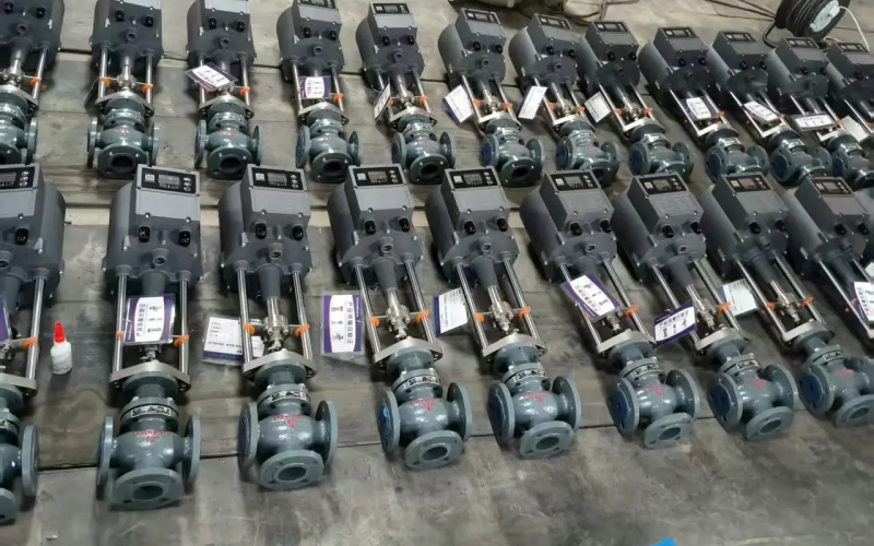
Choosing a control valve size is a calculation followed by a judgement. The calculation gives the flow coefficient the duty demands, and the judgement picks a valve from the manufacturer table whose rated coefficient puts the operating points in the right part of the travel. An undersized valve cannot deliver the maximum flow, and an oversized one spends its life near the seat, where it controls coarsely and erodes the trim. This article walks through the full procedure for liquid duty, explains where gases and steam differ, and shows how to check the result before the valve is ordered.
Information Needed Before Sizing
Collect the duty data before touching a formula. The maximum and minimum flow rates come from the process, and the minimum matters as much as the maximum because it decides whether the valve can control at low load. The pressures are the upstream pressure and the allowable pressure drop at maximum flow. That drop is often not the full line pressure. If the pump or the upstream regulator has a flat curve, the drop available to the valve shrinks as flow rises, and sizing against the wrong drop is one of the most common errors in the whole exercise. The fluid properties complete the list: specific gravity for a liquid, and for gases or steam the molecular weight, inlet temperature and critical properties, which is why gas sizing belongs to the manufacturer calculation covered later.
Liquid Sizing, Step by Step
For liquid service the required coefficient follows from the maximum flow, the specific gravity and the allowable pressure drop:
Cv = Q × √(Gf / ΔP)
with Q in US gallons per minute and ΔP in psi, or in metric form with Kv, Q in cubic meters per hour and ΔP in bar. The worked example below uses metric units. Water at 20 °C, maximum flow 20 m³/h, allowable pressure drop 0.8 bar, specific gravity 1. The required Kv is 20 × √(1 / 0.8) ≈22.4.
Add the sizing margin before comparing with the table. A valve selected to sit at full stroke at maximum flow leaves no room for pump curve uncertainty, fouling or future rate increases, so the common practice is to multiply the required coefficient by about 1.3. That gives 22.4 × 1.3 ≈29.1 as the target rated Kv. From the typical Kv table for single-seated control valves, the DN50 size with a rated Kv of about 38 is the nearest standard size above the target, and that becomes the candidate.
| Step | Calculation | Result |
|---|---|---|
| Required Kv at maximum flow | 20 × √(1 / 0.8) | ≈22.4 |
| Target rated Kv with 30 % margin | 22.4 × 1.3 | ≈29.1 |
| Selected valve size | DN50, rated Kv ≈38 | 38 ≈29.1, passes |
| Opening at maximum flow | 22.4 / 38 against equal percentage curve | ≈84 % |
| Opening at minimum flow, 2 m³/h | 2.2 / 38 against equal percentage curve | ≈17 % |
At maximum flow the valve sits around 84 % open, which is where a control valve should spend its hardest working moment, close to full stroke but with a little travel in reserve. At minimum flow it still sits near 17 % open, comfortably above the low end of the range, so the full duty fits the valve.
Checking the Travel: Characteristic and Rangeability
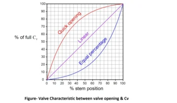
The travel check turns the flow coefficient into an opening position, and it needs the flow characteristic and the rangeability. For an equal percentage valve, each equal step of travel multiplies the flow by a constant factor, which is why the opening at a given flow can be found from the ratio of the required Kv to the rated Kv. Rangeability, typically 30:1 for control valves in this class, states the ratio between the maximum controllable flow and the smallest flow the valve can still regulate. In the example the rated Kv of 38 divided by 30 gives a minimum controllable Kv of about 1.3, which corresponds to roughly 1.1 m³/h of water. The stated minimum of 2 m³/h sits well above that limit, so the low end is safe.
Linear characteristics follow the same idea with a different curve. The opening check should always be run against the actual characteristic of the chosen valve, because the same ratio of flows lands at a different travel on a linear curve than on an equal percentage curve. If the minimum flow lands below about 10 % travel, the valve is too large for the duty regardless of what the maximum-flow calculation says.
Gases and Steam: A Different Calculation
The liquid formula stops being valid once the fluid is compressible. For gases and steam the density changes through the valve, and above a critical pressure ratio the flow chokes, meaning it depends on the inlet pressure and no longer on the downstream pressure. For steam the critical ratio sits near 55 percent, and for gases it follows from the specific heat ratio of the gas. In choked flow the required coefficient grows with the absolute inlet pressure and the flow, not with the pressure drop, and an undersized valve on gas duty is often the result of applying the liquid formula and getting a coefficient that looks generous but is wrong.
This is the point where a manufacturer sizing calculation earns its keep. The calculation handles the compressibility factor, the critical flow, the recovery behaviour of the trim and the noise estimate in one pass, and it returns the coefficient plus a predicted sound level. A written enquiry with the inlet pressure, the outlet pressure or allowable drop, the flow, the temperature and the gas properties is all the manufacturer needs. Anyone who needs the background before sending that enquiry can start with the definitions and basics in our article on control valve Kv and Cv values.
Margin, Oversizing and Common Mistakes
The margin exists to absorb what the calculation cannot see. Pipe friction estimates, pump curve tolerances, future process changes and internal fouling all eat into the available coefficient, and a valve with no margin becomes a bottleneck at the worst moment of the year. About 30 percent is the usual starting figure, with more for uncertain duties and less for a well-defined constant flow.
Oversizing is the mirror image and it is just as damaging. A valve that is far too large controls from the bottom of its travel, where an equal percentage curve is steep and the same stem movement produces a tiny, hard-to-repeat flow change. The result is hunting, poor set point holding and accelerated seat and plug wear at small openings. The classic mistakes are easy to list: sizing on the line pressure instead of the available drop, applying the liquid formula to gas, forgetting the minimum flow, adding a margin on top of an already generous pump, and skipping the noise check on high pressure drop gas duty. Each one puts the valve in the wrong part of its travel, which is exactly what the travel check exists to catch.
Conclusion
Sizing a control valve comes down to three numbers that have to agree: the required coefficient at maximum flow, the rated coefficient of the chosen size, and the travel at minimum flow. The liquid formula gives the first, the manufacturer Kv table gives the second, and a characteristic and rangeability check gives the third, with a 30 percent margin keeping the result honest. Gases and steam move to the manufacturer calculation because choking changes the rules, and the travel check stays the final gate in every case. A valve that passes all three will spend its working life between about 15 and 90 percent travel, which is where control valves control best.
 No products in the cart.