
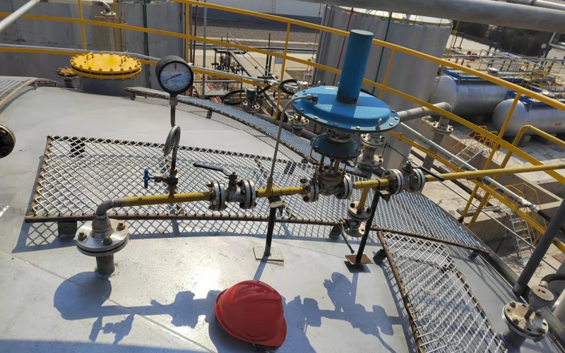
Storage tanks hold liquids that have to stay clean, stable and safe for weeks or months at a time, and the space above the liquid is where most of the trouble starts. When the tank breathes, moist air gets in, oxygen reacts with the product, vapour escapes and is lost, and with flammable liquids a flammable atmosphere can form. Nitrogen blanketing, sometimes called padding or inerting, fills that space with dry nitrogen held at a slight positive pressure, so the product never meets air. Keeping that small pad pressure inside its working band is the job of the blanketing system, and each valve in it has a distinct role.
Why Tanks Need Blanketing
Four problems push storage tanks toward nitrogen blanketing. Oxidation is the first: many hydrocarbons, solvents and food or chemical products degrade when oxygen reaches them, which shows up as discolouration, gum formation, corrosion of the tank wall or a shorter shelf life. Vapour loss is the second. A tank that breathes freely loses product vapour on every warm cycle, which costs money and creates an odour or emission problem at the same time. Moisture is the third, since humid air condenses inside the tank and contaminates water-sensitive products or supports microbial growth. The fourth is fire safety. For flammable liquids, keeping the oxygen concentration in the vapour space below the limiting oxygen concentration removes one side of the fire triangle, and nitrogen is the usual way to do it.
Blanketing addresses all four with one simple arrangement. The tank vapour space stays filled with nitrogen at a small positive pressure, so the only gas that can enter when the tank breathes in is nitrogen, and the product itself never sees air.
How a Blanketing System Works
Three functions have to be covered. The blanketing valve, also called the supply regulator, adds nitrogen when the pressure falls. A pressure relief path vents vapour or nitrogen when the pressure rises above the set point. And a vacuum protection path admits air or nitrogen when the tank would otherwise be pulled below its design vacuum. The relief and vacuum functions are often combined in one pressure vacuum relief valve, or handled separately, depending on the tank and the local code.
Normal operation is a continuous small cycle rather than a one-time fill. When product is pumped out or the tank cools at night, the vapour space grows and the pressure drifts down. The blanketing valve opens, admits nitrogen and brings the pressure back to its set point. When product is pumped in or the sun heats the tank, the pressure rises and the relief path vents the excess. The blanketing valve is the trim control of this loop, while the relief valves are the safety nets, so their set points must not overlap.
The Blanketing Valve
Most tank blanketing valves are self-operated, direct-acting regulators. They need no electric power and no instrument air, which suits remote tank farms where neither is guaranteed. The valve is normally closed. A spring, often assisted by a pressure-loaded reference, holds the closing force, and the tank pressure acts against it. When the tank pressure drops below the set point by a small amount, the valve lifts and nitrogen flows in. As the pressure recovers toward the set point, the valve throttles back and finally seats again. The set point is adjusted with the spring, and typical units for NW VALVE tank blanketing regulators such as the ZZVP and ZZYVP series are set in the range of a few kilopascals, at water-column level.
Because the working band is so narrow, a blanketing valve has to be sensitive and stable. It must open on a pressure change of a few hundred pascals, pass enough nitrogen at a very low pressure drop, and close bubble-tight so nitrogen is not wasted while the system sits at its set point. Small body sizes cover most duties, and carbon steel or stainless steel bodies with elastomer or PTFE seating are the common options.
Set Points and Working Ranges
Pad pressures are low, normally a fraction of the tank design pressure. The exact set points come from the tank designer and from standards such as API 2000, and they should be written down, not improvised on site. The bands below show typical practice for common services and are a starting point for discussion with the tank designer.
| Tank Service | Typical Blanketing Range |
|---|---|
| Fixed-roof tank, light hydrocarbons or solvents | 0.5 to 1.5 kPa (50 to 150 mmWC) |
| Fixed-roof tank, water-based liquids or general chemicals | 0.3 to 1.0 kPa (30 to 100 mmWC) |
| Process vessel or reactor under inerting | 1 to 2 kPa (100 to 200 mmWC) |
The working band must sit comfortably between the vacuum protection set point below it and the pressure relief set point above it. If the three set points crowd together, normal breathing alone can start the safety valves, which wears them and wastes nitrogen.
Sizing a Blanketing Valve
A blanketing valve is sized for the worst out-breathing case, when the tank needs nitrogen fastest. That happens during maximum product withdrawal, combined with cold weather shrinkage of the vapour space. The standard method, described in API 2000, sums the flow from pump-out, thermal contraction and liquid level changes to find the maximum in-breathing rate. The relief path is sized for the opposite case, maximum pump-in plus thermal expansion and vapour generation. The blanketing valve should respond before the vacuum protection opens, which means the supply path has to be fast enough to cover normal in-breathing without calling on the safety device.
Once the maximum nitrogen flow is known, the required Kv is calculated for gas service, which involves the inlet pressure, the compressibility of nitrogen and the choked flow limit. A common error is to treat the pad as a normal pressure-reducing duty and oversize the valve. Oversizing makes the regulator hunt around its set point, and the tank pressure swings instead of holding steady. A manufacturer sizing calculation, or a written enquiry with the tank data, is the reliable route.
Selection Notes
The blanketing valve itself is only one part of the supply train. The nitrogen supply should be regulated and filtered before it reaches the blanketing valve, so the valve sees a steady inlet pressure and clean gas. Moisture in the nitrogen is a real concern in winter, since ice in the pilot or on the seat stops the valve from sealing, and a dryer upstream is often worth the cost. Check the materials against the vapour above the stored liquid, not just against nitrogen, because that vapour condenses back on the valve internals.
For the same reason, trim and seating that give a tight shutoff matter more here than in most control valve services. A small internal leak in a blanketing valve is invisible during the day and shows up only as a nitrogen bill at the end of the month. If remote indication of valve position or tank pressure is wanted, a limit switch or a simple pressure transmitter can be added without changing the valve itself.
Common Problems and Checks
Several failures show up again and again in blanketing service. Low or collapsing tank pressure usually means the supply is short, from a low nitrogen header pressure, a fouled filter, or a blanketing valve whose Kv is below the pump-out demand. Persistently high pressure points to a leaking blanketing valve seat, a relief set point set too close, or a regulator that hunts because it is oversized. Rising nitrogen consumption with no obvious process change is the classic sign of internal leakage and deserves a seat inspection before the bill grows. Frozen pilots and seats appear in cold weather when the gas is wet, and chattering or rapid cycling usually traces back to an unstable supply pressure or a valve that is too large for the duty.
Most of these problems are caught by watching two things: the trend of the tank pressure and the nitrogen usage. A steady pad pressure with a modest, predictable nitrogen flow means the system is healthy. Frequent relief venting, pressure alarms or a climbing nitrogen bill all say the same thing, that one of the three valves is no longer doing its share.
Conclusion
A tank blanketing system is a small pressure loop built from three valves with separate jobs. The blanketing valve trims the pad, the relief path protects the high side and the vacuum protection covers the low side, and the whole loop works only when the set points are spaced properly and the supply is clean and dry. Set points belong to the tank designer and to API 2000, while valve sizing should follow the worst pump-out and pump-in cases with a proper gas calculation. Handled that way, nitrogen blanketing is one of the most dependable duties a small regulator can perform.
 No products in the cart.