
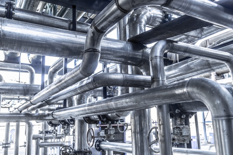
Boilers and distribution mains run at pressures and temperatures chosen for efficiency, while most processes need steam at far milder conditions. Between the two sits the reduction station, and getting it right matters more than the piping around it suggests. Throttling steam to lower the pressure leaves the temperature almost unchanged, since the expansion is close to isenthalpic, so a high-pressure line reduced in pressure alone comes out with a higher degree of superheat. That overheated steam is harder on heat exchangers, tracing and control valves than saturated steam at the same pressure. A complete station therefore reduces pressure and temperature together, and this article walks through the valves that do each job.
Why Steam Pressure and Temperature Are Reduced
Three reasons cover most installations. The first is matching supply to process. A plant may generate steam at 1.0 MPa to serve a whole site, while a reactor jacket, a heat exchanger or a sterilization loop needs steam at 0.3 MPa, and every user taps off the same header. The second is protecting downstream equipment. Jackets, gaskets and instruments are rated for a design pressure and temperature, and feeding them steam above the rating shortens their life or voids their certification. The third is control quality. Saturated steam at a stable pressure gives predictable heat transfer, which is what temperature control loops assume, and dropping superheated steam directly into a process complicates that assumption.
There is also an efficiency angle. Generating and distributing at higher pressure keeps pipe sizes and steam velocities down, then reducing at the point of use gives each process the exact condition it needs. The station is where that flexibility is bought, and it is built around two control loops, one for pressure and one for temperature.
How a Reduction Station Is Laid Out
A typical station handles pressure and temperature as separate duties. The pressure reducing valve takes the upstream steam and holds the downstream pressure at its set point. The desuperheater, usually located after the pressure reducing valve, injects water to bring the temperature down to the target. Downstream of both, the steam is close to saturated at the reduced pressure. Around this core sit a safety relief valve sized for the worst credible case, condensate removal at every low point, and instrumentation for pressure, temperature and flow.
| Station Element | Job in the Station |
|---|---|
| Pressure reducing valve | Holds downstream pressure at set point across the load range |
| Desuperheating water valve | Meters cooling water against measured steam temperature |
| Safety relief valve | Protects downstream piping and equipment if the reducing valve fails open |
| Condensate traps and drains | Keep the line dry during warm-up and normal running |
Reducing pressure first and temperature second is the common sequence. If the order were reversed, the temperature control would be trying to manage steam that is about to change pressure, and the interaction between the two loops becomes harder to tune. Separate the duties and each loop has one variable to watch.
Pressure Reduction
The pressure reducing valve is a control valve in a pressure loop. Its sensor is the downstream pressure, and its actuator can be self-operated, pneumatic or electric. Self-operated reducing valves use the downstream pressure against a spring or a pilot and need no external energy, which suits small stations and remote locations. Pneumatic valves with a positioner give tighter control and easier set point changes from a control room, and electric actuators fit sites where instrument air is not available.
Steam service shapes the valve choice. Because the fluid is dry, fast and abrasive at high velocities, the trim sees erosion rather than corrosion in most cases, and hardened seats and plugs extend service life. The body and bonnet must handle the temperature, with graphite or other high-temperature packing above roughly 200 °C. A common arrangement for wide load swings is two reducing valves in parallel, one sized for the base load and one for the peak, so neither spends its life at a tiny opening.
Desuperheating
Desuperheating removes the superheat by injecting water directly into the steam flow. The water flashes to steam and absorbs heat, and the amount injected is set by a control valve driven from a downstream temperature measurement. The water control valve is the heart of this loop. It has to respond quickly, since the temperature measurement is downstream and the loop has dead time, and it has to meter small flows accurately when the demand is low.
The process imposes two practical limits. There must be enough superheat at the injection point for the water droplets to evaporate completely, otherwise wet steam or water slugs reach the process. And the controlled temperature should stay above saturation, because once the steam is saturated the temperature no longer follows the water flow. That is why the set point is written as a temperature above saturation for the reduced pressure, not as saturation itself.
Choosing Valves for Steam Duty
Material and trim selection for steam follows the temperature and the pressure drop. Carbon steel bodies cover the majority of steam stations up to roughly 425 °C, with alloy steel or stainless steel where the temperature climbs higher. The trim should be erosion resistant for the pressure reducing valve, since the highest velocity sits right at the seat and plug. For the desuperheating water valve, the water is clean but the pressure drop is large, so cavitation resistance and a tight shutoff matter, and hardened trim again earns its cost.
Packing and bonnet design follow the temperature as well. Standard PTFE packing suits moderate steam, while graphitic packing and a finned or extended bonnet are used at higher temperatures to keep the packing area cool. Leakage class is worth specifying explicitly. A class IV metal seat is typical for the reducing valve, and if the station must hold pressure when closed, soft seating or a higher class should be discussed with the manufacturer rather than assumed.
Sizing Notes
Steam sizing is a gas sizing problem with one extra feature. Above a critical pressure ratio, roughly 55 percent for steam, the flow through the valve chokes and depends only on the inlet pressure, not on the downstream pressure. The required coefficient is therefore calculated from the inlet conditions and the critical flow, and the downstream pressure enters only when the drop is subcritical. This is not the place for the liquid formula from general valve sizing, and a manufacturer sizing calculation, or a written enquiry with inlet pressure, outlet pressure, flow and temperature, is the dependable route.
Noise deserves a check at the same time. High pressure drops across a steam valve generate high noise levels, and the attenuation of the downstream pipe, or the need for a low-noise trim, should be part of the selection. So should the failure position of the valve. If the reducing valve fails open, the safety relief valve downstream has to handle full upstream flow, and the relief valve is sized for exactly that case, not for the normal operating flow.
Safety and Commissioning
Commissioning a steam station follows a fixed routine for a reason. The line is warmed slowly with the drains open, so condensate leaves before the valves see full flow, and water hammer is avoided. The reducing valve is then set progressively, watching the downstream pressure rather than opening it fully at once. The safety relief valve setting and the reducing valve set point must leave a clear margin between them, since a relief valve that lifts during normal control is a sign of a mis-set station, not a faulty one.
Condensate is the quiet enemy of the whole station. Traps at the inlet of the reducing valve and at low points of the downstream line keep water out of the valve bodies, where it would cause wire drawing and erosion when it flashes. A station that drains properly, warms up slowly and never lifts its relief valve during normal running will give years of service with little more than packing and seat attention.
Conclusion
A steam pressure and temperature reduction station separates two duties and controls them independently. The pressure reducing valve holds the downstream pressure while the desuperheater trims the temperature, and each valve is sized and selected for the conditions it actually sees, superheated steam for one and high-pressure water for the other. The set points leave room between normal control and the safety relief, and commissioning follows the slow, dry warm-up that steam demands. On those terms a reduction station is straightforward to run, and most of its failures trace back to wet steam or a relief valve that was never meant to lift.
 No products in the cart.