
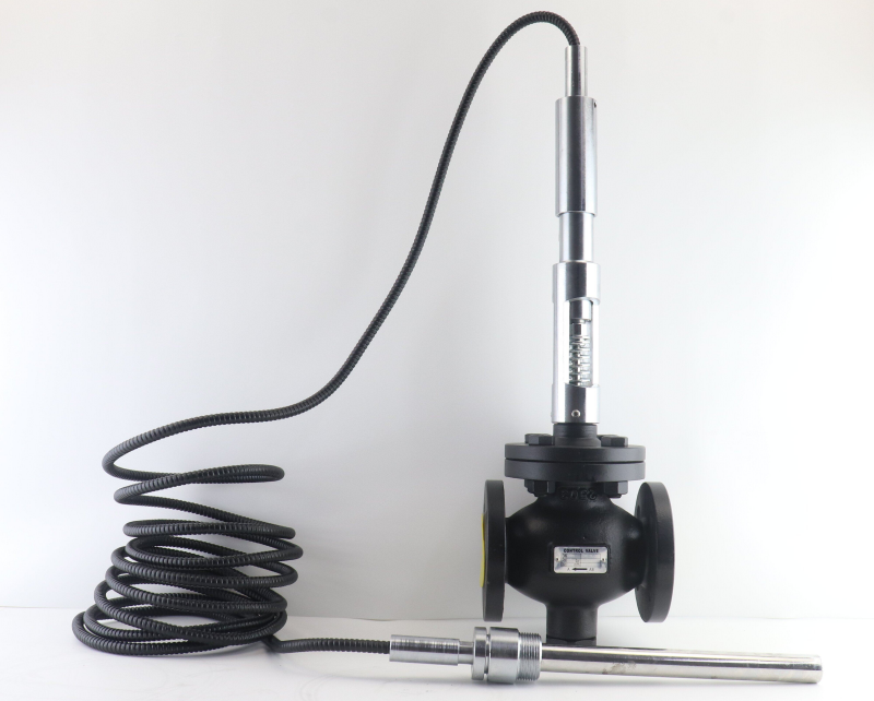
Temperature Control in Heat Exchange Stations: The Central Nervous System of Heating
A heat exchange station is the key hub connecting the primary heating network to the secondary user side in a district heating system. Its core task is to transfer heat from the primary network (high-temperature hot water or steam) to the secondary-side circulating water through heat exchangers, and to hold the secondary supply water temperature precisely within the design range.
Of all the control loops in a heat exchange station, temperature control is the most critical and directly affects user comfort. If the secondary supply temperature runs high, rooms overheat and energy is wasted; if it runs low, users complain that their rooms never reach the required level. The quality of temperature control depends largely on the selection and installation of the temperature regulating valve.
Typical control schemes for heat exchange station temperature control
Two mainstream temperature control schemes are used in district heating heat exchange stations:
Scheme 1: Primary-side temperature regulation. A temperature regulating valve is installed on the primary network side. It modulates the primary heat-medium flow according to changes in the secondary supply water temperature: when the secondary supply temperature is too high, the primary-side valve is closed down; when too low, it is opened up, thereby controlling the heat transferred in the exchanger.
Scheme 2: Secondary-side mixing regulation. A three-way regulating valve on the secondary side mixes supply and return water to adjust the supply temperature. This scheme is mostly used in low-temperature floor radiant heating systems.
Of the two, Scheme 1 (primary-side regulation) is the most widely applied and the most energy-efficient, and it is exactly the duty in which self-operated temperature regulating valves excel.
Why Self-Operated Temperature Regulating Valves Suit Heat Exchange Stations
Two main options are available for temperature regulating valves in heat exchange stations: self-operated temperature regulating valves and electric temperature control valves. The choice should be based on the station’s actual operating conditions and maintenance capability.
Characteristics of the heating scenario
Continuous 24/7 operation. During the heating season, heat exchange stations run around the clock; any interruption of heating becomes a complaint event. Self-operated temperature regulating valves are purely mechanical, with no aging of electrical components, no power failure and no control-system crashes, giving extremely high long-term reliability.
Freeze protection requirements. Outside the heating season or during the early heating period, stations may run at low load, with a risk of pipe freezing. Self-operated temperature regulating valves do not depend on external power: even if the station suffers a power outage, the sensing system continues to adjust the valve opening automatically according to water temperature, providing freeze protection.
Variable operating environments. Most heat exchange stations are located in basements or old residential areas, which tend to be humid and dusty and often have only average power supply conditions. Self-operated valves need no electrical cabinet or control system, so their environmental adaptability is far superior to that of electric solutions.
Limited maintenance staff. Heating companies typically manage dozens or even hundreds of heat exchange stations and cannot patrol them daily. Self-operated valves offer long maintenance-free intervals, substantially reducing the maintenance workload.
Self-operated vs electric: comparison for heat exchange stations
| Comparison Dimension | Self-Operated Temp Regulating Valve | Electric Temp Control Valve |
|---|---|---|
| Power dependency | No external power required | Requires 220 V AC + PLC control |
| Freeze protection | Still regulates automatically during power outage; reliable freeze protection | Valve stays in position after power loss; freezing risk |
| Maintenance workload | Maintenance-free; annual inspection | Regular inspection of actuator and control system |
| Installation cost | Valve body + bracket; install and use | Valve + actuator + control cabinet + sensors + wiring |
| Control accuracy | ±2-3 °C (fully adequate for heating) | ±0.5-1 °C (usually over-specified for heating) |
| Applicable scenarios | Unattended stations; retrofitting older stations | Large regional stations; systems requiring remote centralized control |
In the heat exchange station scenario, self-operated temperature regulating valves offer clear combined advantages in reliability, economy and ease of maintenance. Only when a station already has a complete building automation system (BAS) and needs remote centralized monitoring should the electric solution be given priority.
Key Selection Parameters for Self-Operated Temperature Regulating Valves
The following five parameters are the core basis for selecting a self-operated temperature regulating valve for a heating heat exchange station.
Parameter 1: Heating load and valve size
The valve size is determined by the design heating load of the station, usually provided by the thermal design engineer in MW or GJ/h. The heating load is used to calculate the heat-medium flow through the valve, and the valve size is then determined together with the differential pressure across the heat medium.
Reference table of experience values (steam primary side, steam pressure 0.6 MPa):
| Heating Load (MW) | Steam Flow (t/h) | Recommended Valve Size |
|---|---|---|
| 2-4 | 3-6 | DN50 |
| 4-8 | 6-12 | DN65-DN80 |
| 8-14 | 12-21 | DN100 |
| 14-22 | 21-33 | DN125-DN150 |
Note: the values above are for reference only. Actual selection should be based on the manufacturer’s sizing calculation.
Parameter 2: Primary-side media parameters (temperature and pressure)
Primary networks in heat exchange stations come in two common forms:
- Steam heat exchange stations: the primary side carries steam, usually at the saturation temperature corresponding to its pressure. Superheat, pressure reduction ratio and cavitation risk should be considered during selection.
- Hot water heat exchange stations: the primary side carries high-temperature hot water, with a supply temperature typically of 95-130 °C and a return temperature of 50-70 °C.
The media parameters determine the choice of valve body material, sealing material and packing type.
Parameter 3: Secondary supply temperature set range
The secondary supply temperature is the setpoint of the temperature regulating valve, and is determined by the type of heating system:
| Heating Form | Secondary Supply Temperature Range | Recommended Control Accuracy |
|---|---|---|
| Radiator heating | 70-85 °C | ±3 °C |
| Floor radiant heating | 35-50 °C | ±2 °C |
| Fan coil unit systems | 50-60 °C | ±2 °C |
The set temperature of a self-operated temperature regulating valve is adjusted by changing the spring preload or using the setting knob of the sensing element. The temperature range can be preset at the factory or adjusted on site.
Parameter 4: Sensing element type and capillary length
The sensing element is the “temperature sensor” of a self-operated temperature regulating valve. Three common types are used:
- Liquid expansion type: the bulb is filled with a sensing liquid whose volume changes with temperature. High accuracy with moderate response speed, suitable for most heat exchange station temperature ranges (30-120 °C).
- Gas expansion type: filled with inert gas, giving the fastest response; suitable for applications sensitive to control response.
- Vapor pressure type: uses the saturated vapor pressure of a low-boiling-point liquid. Moderate accuracy but simple construction and low cost.
Capillary length determines the distance between the sensing bulb and the valve body. Standard lengths are 3-5 m; for heat exchange stations, 3 m or more is recommended so that the bulb can be installed far enough from the heat exchanger to avoid interference from its radiated heat.
Parameter 5: Valve connection type and installation space
Piping space inside a heat exchange station is often limited. The valve connection type (flanged, threaded or welded) must match the end-face standard of the primary-side piping. Self-operated temperature regulating valves are normally supplied with flanged connections (ANSI or DIN standard); the flange standard must be confirmed against the mating piping during selection.
Installation Essentials: Bulb Position and Capillary Routing
The installation quality of a self-operated temperature regulating valve directly affects the temperature control result. The following three points are the most common “make-or-break details” on site.
Selecting the bulb position
The sensing bulb must be installed where it accurately reflects the secondary supply water temperature. Positions in order of priority:
- Optimal position: on the secondary supply pipe, 3-5 pipe diameters downstream of the heat exchanger outlet, away from the heat exchanger’s radiated heat zone.
- Second choice: on the secondary supply water collector, provided the water temperature in the collector is uniform.
- Positions to avoid: pipe dead ends, bottom sediment zones, and locations close to bypass pipes.
The bulb should be fully inserted into the pipe, immersed in the flowing medium, and installed as coaxially as possible with the pipe centerline. For large-bore pipes (DN200 and above), a thermowell is recommended so that the bulb can be removed for maintenance and replacement.
Capillary routing and protection
The capillary is the “signal line” between the sensing bulb and the actuator; once damaged, the valve loses its temperature control capability. Site rules to follow:
- Route the capillary along the piping and fix it with pipe clamps; avoid dangling sections.
- Keep a natural bend radius at corners (not less than 50 mm); do not kink or sharply fold the capillary.
- Avoid contact between the capillary and hot pipe surfaces; add an insulating layer where necessary.
- Use protective sleeves where the capillary passes through walls or floors.
Valve orientation and space
The valve body of a self-operated temperature regulating valve should be installed horizontally on the primary-side pipe with the actuator facing upward. Reserve a straight run of 3-5 pipe diameters upstream of the valve and 2-3 diameters downstream to keep the flow pattern stable. A Y-type strainer should be installed upstream to prevent line debris from damaging the sealing surfaces.
Seasonal Commissioning and Maintenance
Commissioning before the heating season
The following checks should be carried out every year before the heating season starts:
- Check the set temperature: confirm the secondary supply temperature setpoint against the current heating plan, and adjust the setting knob or spring.
- Vent air: open the vent at the sensing bulb to remove air from the bulb (especially important for gas expansion types).
- Observe the temperature response: after start-up, watch the secondary supply temperature curve and confirm the valve stabilizes near the setpoint within 30-60 minutes.
- Freeze check: inspect the insulation of exposed valve parts and ensure no capillary sections are left bare.
Monitoring during the peak heating period
In the depths of winter, pay particular attention to:
- Whether the secondary supply temperature stays stable within the design value ±3 °C.
- Unusual vibration or noise from the actuator.
- Leakage at the valve body surface or packing.
- Strainer differential pressure (a high reading indicates a clogged screen that needs cleaning).
Maintenance after the heating season
After heating ends, the following maintenance is recommended:
- Leave the spring relaxed (set the setpoint to minimum to release spring stress).
- Open the valve fully and flush the piping to remove deposits accumulated during the heating season.
- Carry out a visual inspection and re-tighten the packing gland if seepage is found.
- Keep the valve identification and operation records as a reference for the next heating season.
Summary: Selection Path for Temperature Regulating Valves in Heat Exchange Stations
Step 1: Determine the station type and heating parameters. Identify the primary heat medium (steam or hot water) and the secondary heating form (radiators, underfloor heating or fan coil units), and collect the basic parameters such as heating load, media temperature and pressure.
Step 2: Select the self-operated temperature regulating valve. Determine the valve size (based on flow calculation), choose the sensing element type (liquid expansion is recommended for its wide temperature coverage), specify the capillary length (3-5 m recommended), and confirm the flange standard and connection type.
Step 3: Technical confirmation with the supplier. Submit a complete selection parameter sheet and obtain the manufacturer’s sizing calculation; confirm that the control accuracy class meets the duty requirements; and confirm delivery time and spare parts availability.
Step 4: Installation and commissioning. Lay out the piping, install the bulb and route the capillary according to the installation specification, and complete system commissioning and calibration before the heating season begins.
 No products in the cart.