
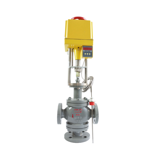
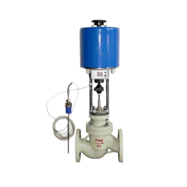
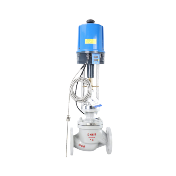
Overview
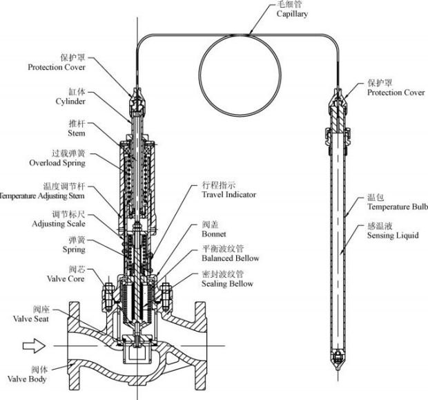
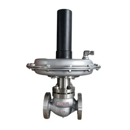
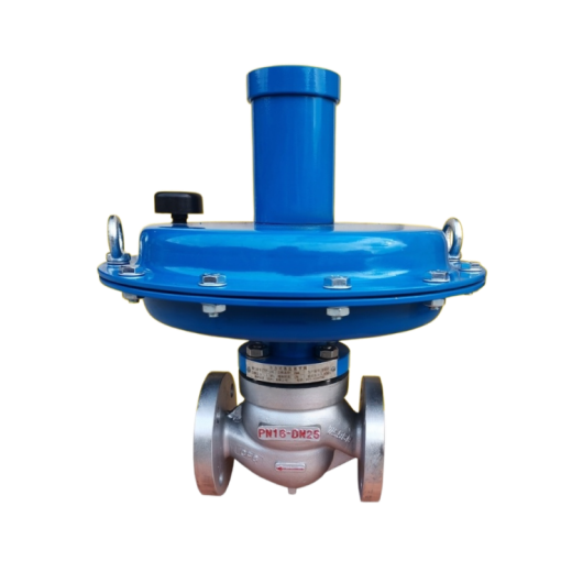
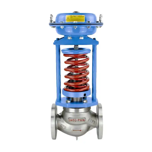
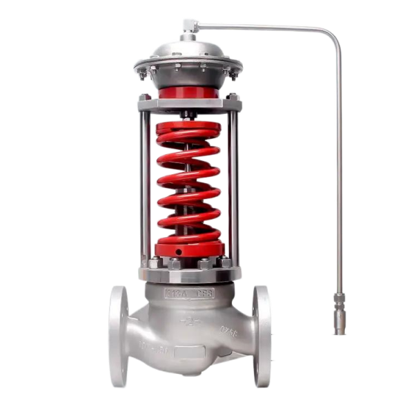
ZZWPE self-operated electric temperature regulating valve is suitable for large-diameter pipelines and heat transfer oil control. Its biggest advantage is that it only requires ordinary 220 V AC power supply. Using the energy of the controlled medium itself, it automatically regulates and controls the temperature of steam, hot water, hot oil, gas and other media directly. It can also be used for over-temperature protection or heat exchange applications. The valve features simple structure, convenient operation, wide applicable temperature adjustment range, fast response and reliable sealing performance, and can be freely adjusted during operation. It is therefore widely used for hot water supply in chemical, petroleum, food, textile, hotel and restaurant industries.
ZZWPE control valve covers nominal diameters from 20 to 200 mm and nominal pressures of 1.0, 1.6, 4.0 and 6.4 MPa, with a service temperature range from -40 °C to +450 °C. It accepts 0-10 mA DC or 4-20 mA DC signals to change the flow rate of the controlled medium, keeping the controlled process parameters at the set value. The single-seat regulating type is suitable for applications with small differential pressure, high medium viscosity or slight particle impurities, while the cage regulating type is suitable for applications with large differential pressure.
Control Valve Technical Parameters
|
Nominal Diameter DN (mm)
(Valve Seat Diameter dn) |
20
|
25
|
32
|
40
|
50
|
65
|
80
|
100
|
125
|
150
|
200
|
||||
|---|---|---|---|---|---|---|---|---|---|---|---|---|---|---|---|
| (10) | (12) | (15) | (20) | ||||||||||||
| Rated Flow Coefficient Kv | Linear | 1.8 | 2.8 | 4.4 | 6.9 | 11 | 17.6 | 27.5 | 44 | 69 | 110 | 176 | 275 | 440 | 690 |
| Equal Percentage | 1.6 | 2.5 | 4 | 6.3 | 10 | 16 | 25 | 40 | 63 | 100 | 160 | 250 | 400 | 630 | |
| Rated Stroke (mm) | 16 | 25 | 40 | 60 | |||||||||||
| Nominal Pressure PN (MPa) | 1.0, 1.6, 4.0, 6.4 | ||||||||||||||
| Inherent Flow Characteristic | Linear, equal percentage | ||||||||||||||
| Inherent Rangeability | 50 | ||||||||||||||
| Allowable Leakage | Single-Seat | Hard seat: Class IV; soft seat: Class VI | |||||||||||||
| Cage | Hard seat: Class II; soft seat: Class VI | ||||||||||||||
| Working Temperature t (°C) | -20 to 200, -40 to 250, -40 to 450, -60 to 450 | ||||||||||||||
| Signal Range (mA DC) | 0-10, 4-20 | ||||||||||||||
| Action Mode | Reverse-acting, direct-acting | ||||||||||||||
| Ambient Temperature (°C) | Electric control valve: -20 to 70 | ||||||||||||||
| Ambient Humidity | Electric control valve: ≤95% | ||||||||||||||
| Power Supply | 220 V, 50 Hz | ||||||||||||||
The performance specifications of this product comply with GB/T4213-92.
Technical Parameters of the Matching Electric Actuator
|
Nominal Diameter DN (mm)
|
20
|
25
|
32
|
40
|
50
|
65
|
80
|
100
|
125
|
150
|
200
|
|
|---|---|---|---|---|---|---|---|---|---|---|---|---|
| Electric Actuator | Standard Type | ZAZ-60 DKZ-310 |
ZAZ-60 DKZ-310 |
DKZ-410 | DKZ-410 DKZ-510 |
|||||||
| Electronic Type | JHZAZ1 | JHZAZ1 | JHZAZ3 | JHZAZ3 | ||||||||
| Actuator Thrust (N) Full-Stroke Time (s) |
Standard Type | 400 4000 |
400 4000 |
6400 | 6400 16000 |
|||||||
| Electronic Type | 2000 | 4000 | 6000 | 8000 | ||||||||
| Standard Type | 12.5 | 20 | 32 | 48 | ||||||||
| Electronic Type | 30 | 30 | 48 | 60 | ||||||||
| Power Consumption (W) | Standard Type | 28 | 35 | |||||||||
| Electronic Type | 6 | 15 | 25 | 40 | ||||||||
The data in the table are for conventional configurations only; specific selection shall be based on the main parameters and user requirements.
Allowable Differential Pressure
Single-Seat Regulating Type
|
Nominal Diameter (mm)
Thrust (N) |
20
|
25
|
32
|
40
|
50
|
65
|
80
|
100
|
125
|
150
|
200
|
|||
|---|---|---|---|---|---|---|---|---|---|---|---|---|---|---|
| 10 | 12 | 15 | 20 | |||||||||||
| 400 | 3.90 | 2.71 | 1.73 | 0.95 | 0.62 | 0.37 | 0.24 | 0.15 | ||||||
| 2000 | 6.40 | 6.40 | 6.40 | 4.87 | 3.11 | |||||||||
| 4000 | 6.40 | 6.40 | 6.40 | 6.40 | 6.11 | 3.73 | 2.39 | 1.53 | ||||||
| 6000 | 1.38 | 0.91 | 0.54 | |||||||||||
| 6400 | 1.45 | 0.95 | 0.61 | 0.40 | 0.28 | 0.15 | ||||||||
| 8000 | 0.50 | 0.34 | 0.19 | |||||||||||
| 16000 | 0.98 | 0.68 | 0.38 | |||||||||||
Cage Regulating Type
|
Nominal Diameter (mm)
Thrust (N) |
20
|
25
|
32
|
40
|
50
|
65
|
80
|
100
|
125
|
150
|
200
|
|---|---|---|---|---|---|---|---|---|---|---|---|
| 400 | 1.94 | 1.62 | 1.31 | 1.08 | 0.88 | ||||||
| 2000 | 6.40 | 6.40 | |||||||||
| 4000 | 6.40 | 6.40 | 6.40 | 6.40 | 6.40 | ||||||
| 6000 | 6.40 | 6.40 | 6.40 | ||||||||
| 6400 | 6.40 | 6.40 | 6.40 | 6.40 | 6.40 | 6.40 | |||||
| 8000 | 6.40 | 6.40 | 6.40 | ||||||||
| 16000 | 6.40 | 6.40 | 6.40 |
If the allowable differential pressure value is greater than the nominal pressure, the nominal pressure value shall apply.
Performance Specifications
|
No.
|
Item
|
Single-Seat Valve
|
Cage Valve
|
|---|---|---|---|
| 1 | Basic Error (%) | ±2.5 | |
| 2 | Hysteresis (%) | 2.0 | |
| 3 | Dead Band (%) | 3.0 | |
| 4 | Rated Stroke Deviation (%) | +2.5 | |
| 5 | Rated Flow Coefficient Deviation (%) | ±10 | |
| 6 | Inherent Flow Characteristic | Conforms to the slope deviation specified in IEC534-1 and GB/T4213-92 | |
Overall Dimensions
Standard Type (Unit: mm)
|
Nominal Diameter DN
|
20
|
25
|
32
|
40
|
50
|
65
|
80
|
100
|
125
|
150
|
200
|
|
|---|---|---|---|---|---|---|---|---|---|---|---|---|
| A | 460 | 530 | 630 | |||||||||
| B | 230 | 230 | 260 | |||||||||
| H1 | 490 | 540 | 625 | |||||||||
| L | 150 | 160 | 180 | 200 | 230 | 290 | 310 | 350 | 400 | 480 | 600 | |
| H2 | 175 | 180 | 215 | 218 | 230 | 280 | 285 | 315 | 400 | 460 | 540 | |
| H3 | 53 | 57.5 | 70 | 75 | 82.5 | 92.5 | 100 | 110 | 125 | 142.5 | 170 | |
| Weight | PN1.6, 4.0 | 50 | 52 | 54 | 56 | 58 | 75 | 87 | 95 | 132 | 135 | 155 |
| PN6.4 | 53 | 56 | 58 | 65 | 68 | 84 | 110 | 129 | 177 | 180 | 210 | |
Electronic Type (Unit: mm)
|
Nominal Diameter DN
|
20
|
25
|
32
|
40
|
50
|
65
|
80
|
100
|
125
|
150
|
200
|
|
|---|---|---|---|---|---|---|---|---|---|---|---|---|
| D | φ155 | φ162 | φ170 | |||||||||
| H4 | 290 | 325 | 380 | |||||||||
| L | 150 | 160 | 180 | 200 | 230 | 290 | 310 | 350 | 400 | 480 | 600 | |
| H5 | 175 | 180 | 215 | 218 | 230 | 280 | 285 | 315 | 400 | 460 | 540 | |
| H6 | 53 | 58 | 70 | 75 | 82 | 92 | 100 | 110 | 125 | 142 | 170 | |
| Weight | PN1.6, 4.0 | 10 | 12 | 15 | 17 | 18 | 34 | 46 | 54 | 76 | 79 | 100 |
| PN6.4 | 13 | 16 | 19 | 26 | 27 | 43 | 69 | 85 | 120 | 125 | 150 | |
Connection Dimensions & Standards
Flange standard: cast iron flanges per GB4216-84; cast steel flanges per GB9113-88.
Flange sealing face type: PN10 and PN16: raised face; PN40 and PN64: male-and-female face, valve body with female face.
Face-to-face length: GB12221-89.
Jacket insulated type, jacket heat medium connection: butt weld φ18×4.
Valve body flanges and face-to-face distance can be manufactured per the standards specified by the user, such as ANSI, JIS and DIN.
Main Parts Materials
Valve body and bonnet: HT200, ZG230-450, ZG1Cr18Ni9Ti.
Plug: ZG1Cr18Ni9Ti, Stellite hard-facing reinforced PTFE.
Packing: PTFE, flexible graphite.
Stem and bushing: 2Cr13.
Gasket: rubber-asbestos sheet, 10, 1Cr18Ni9Ti asbestos wound gasket.
Bellows: 1Cr18Ni9Ti.


 No products in the cart.