


Overview
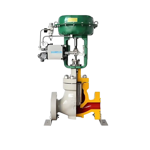
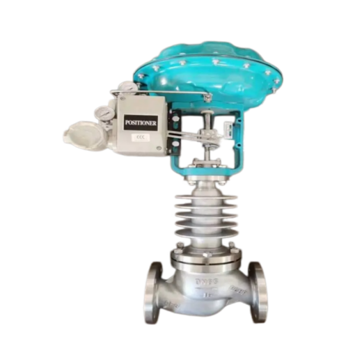
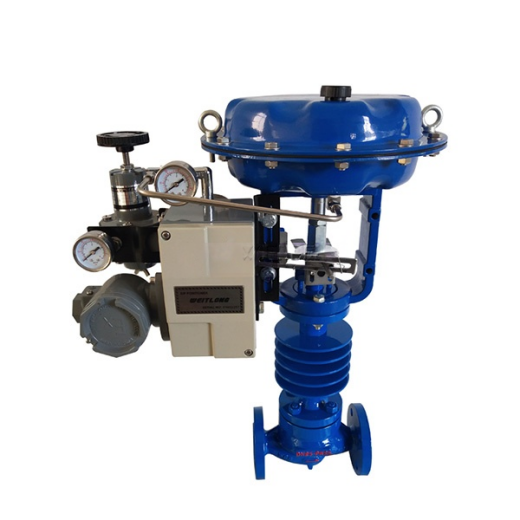
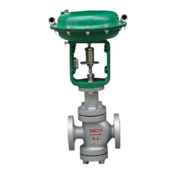
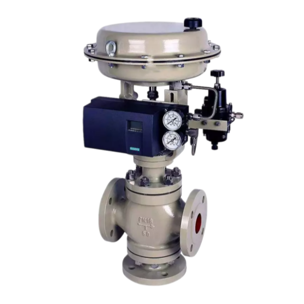
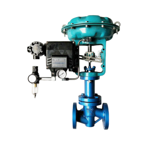
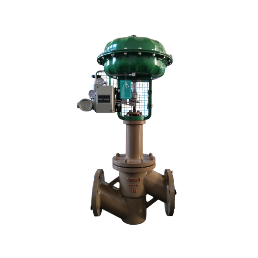
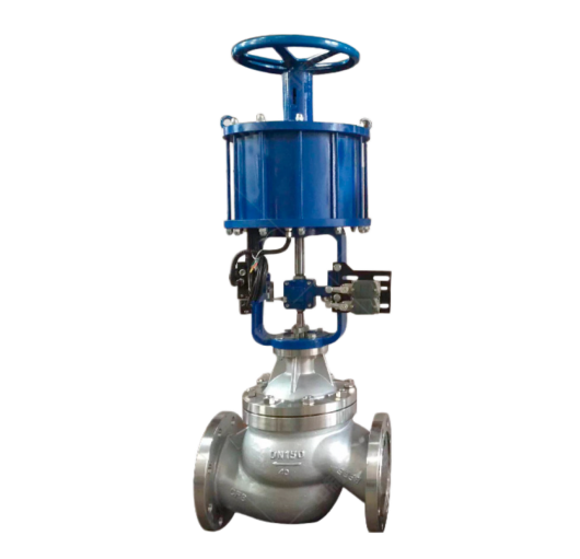
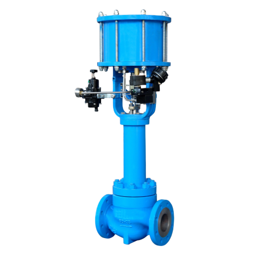
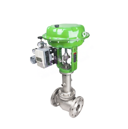
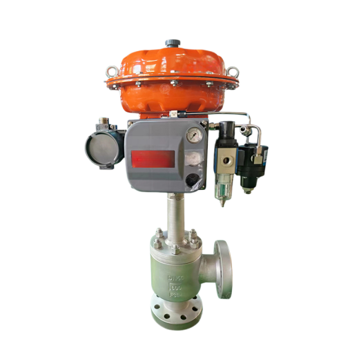
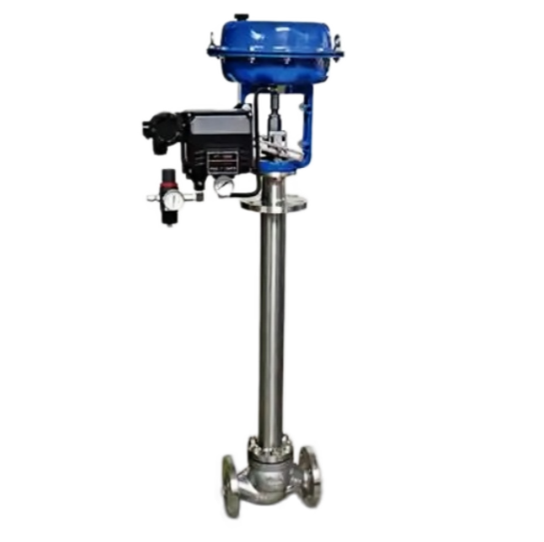
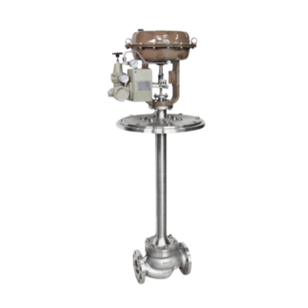
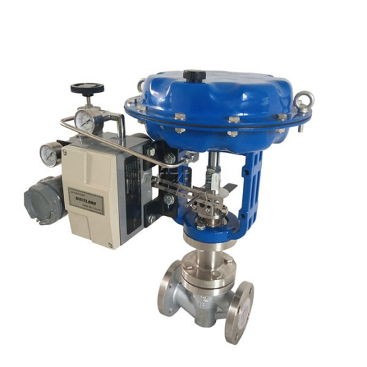
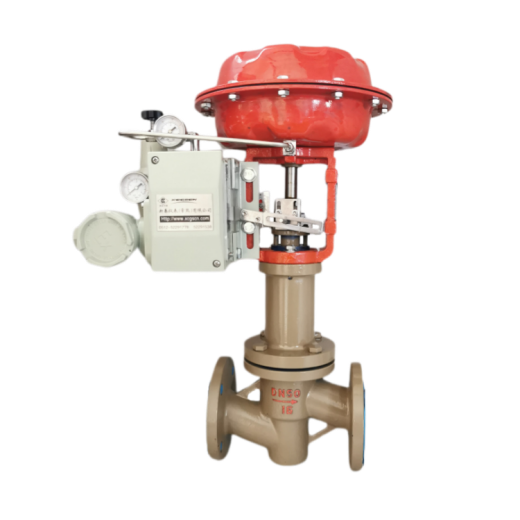
ZJHM pneumatic cage-type control valve features compact size, light weight, high performance and large flow capacity. It is a new-generation general-purpose control valve conforming to IEC standards, suitable for general fluid media and process conditions in production control systems. The valve consists of a new-type pneumatic multi-spring diaphragm actuator and a low-flow-resistance cage valve. Features:
- Balanced plug with small unbalanced force, large allowable differential pressure and stable operation.
- Large plug guiding area reduces oscillation caused by eddy currents and impact, and minimizes damage.
- Noise reduced by about 10 dB compared with ordinary single-seat and double-seat control valves.
- Simple construction, easy assembly, disassembly and maintenance.
Control Valve Technical Parameters
|
Nominal Diameter (mm)
|
25
|
40
|
50
|
65
|
80
|
100
|
150
|
200
|
250
|
300
|
350
|
400
|
||||
|---|---|---|---|---|---|---|---|---|---|---|---|---|---|---|---|---|
|
Seat Diameter (mm)
|
25
|
32
|
40
|
50
|
65
|
80
|
100
|
125
|
150
|
200
|
250
|
300
|
Available on request
|
|||
| Rated Flow Coefficient Kv | Linear | 11 | 17.6 | 27.5 | 44 | 69 | 110 | 176 | 275 | 440 | 690 | 1000 | 1600 | |||
| Equal percentage | 10 | 16 | 25 | 40 | 63 | 100 | 160 | 250 | 400 | 630 | 900 | 1440 | ||||
| Nominal Pressure (MPa) | 0.6 1.6 4.0 6.4 | |||||||||||||||
| Stroke (mm) | 16 | 25 | 40 | 60 | 100 | |||||||||||
| Flow Characteristic | Linear, equal percentage, quick opening | |||||||||||||||
| Medium Temperature (°C) | -40 ~ 230 °C (normal temperature type); 230 ~ 450 °C with cooling-fin bonnet (medium temperature type); -100 ~ 600 °C (special order) | |||||||||||||||
| Flange Standard | Per JB78-59 and JB79-59; also available per JB/79.1-94, JB/79.2-94, ANSI, JIS and DIN | |||||||||||||||
| Body Material | PN (MPa) | 0.6, 1.6 | WCB(ZG230-450) CF3CF8 CF8M | |||||||||||||
| 4.0, 6.4 | WCB(ZG230-450), ZG1Cr18Ni9Ti, ZG0Cr18Ni12Mo2Ti CF8 CF8M | |||||||||||||||
| Body Type | Straight-through single-seat cast globe valve | |||||||||||||||
| Plug Material | 1Cr18Ni9, 0Cr18Ni12Mo2Ti CF8 CF8M | |||||||||||||||
| Bonnet Type | Plain (normal temperature type), cooling-fin (medium temperature type), low temperature type | |||||||||||||||
| Rangeability R | 50:1 | |||||||||||||||
| Air Supply Connection | M16×1.5 | |||||||||||||||
Products with flanges to ANSI, JPI and JIS standards are available on request; face-to-face dimensions determined as required.
Actuator Technical Parameters
|
Model
|
ZHA(B)-22
|
ZHA(B)-23
|
ZHA(B)-34
|
ZHA(B)-45
|
|---|---|---|---|---|
| Effective Area (cm²) | 350 | 350 | 560 | 900 |
| Stroke (mm) | 16 | 25 | 40 | 60 |
| Spring Range (kPa) | 20 ~ 100 (standard); 40 ~ 200; 80 ~ 240; 20 ~ 60; 60 ~ 100 | |||
Performance Specifications
|
Item
|
Value
|
Item
|
Value
|
||||
|---|---|---|---|---|---|---|---|
| Basic Error (%) | Without positioner | ±5.0 | End Point Deviation (%) | Air-to-close | Without positioner | Starting point | ±5.0 |
| End point | ±2.5 | ||||||
| With positioner | ±1.0 | With positioner | Starting point | ±1.0 | |||
| End point | ±1.0 | ||||||
| Hysteresis (%) | Without positioner | 3.0 | Air-to-open | Without positioner | Starting point | ±2.5 | |
| End point | ±5.0 | ||||||
| With positioner | 1.0 | With positioner | Starting point | ±1.0 | |||
| End point | ±1.0 | ||||||
| Dead Band (%) | Without positioner | 3.0 | |||||
| With positioner | 0.4 | Allowable Leakage (L/h) | 1×10⁻³ × rated valve capacity | ||||
| Rated Stroke Deviation (%) | ±2.5 | ||||||
Note: This product conforms to GB/T4213-92.
Allowable Differential Pressure
|
Action
|
Actuator Model
|
Spring Range (kPa)
|
Supply Pressure (kPa)
|
Accessory Required
|
Nominal Diameter (Seat Diameter) (mm)
|
|||||||
|---|---|---|---|---|---|---|---|---|---|---|---|---|
|
25
|
40
|
50
|
65
|
80
|
100
|
150
|
200
|
|||||
| Air-to-close | ZHA-22 | 20 ~ 100 20 ~ 100 40 ~ 200 |
0.14 0.25 0.40 |
– P P or R |
3.00 6.4 6.4 |
|||||||
| ZHA-23 | 20 ~ 100 20 ~ 100 40 ~ 200 |
0.14 0.25 0.40 |
– P P or R |
2.25 6.4 6.4 |
1.95 6.4 6.4 |
|||||||
| ZHA-34 | 20 ~ 100 20 ~ 100 40 ~ 200 |
0.14 0.25 0.40 |
– P P or R |
2.36 6.4 6.4 |
2.04 6.4 6.4 |
1.67 6.4 6.4 |
||||||
| ZHA-45 | 20 ~ 100 20 ~ 100 40 ~ 200 |
0.14 0.25 0.40 |
– P P or R |
1.41 6.4 6.4 |
1.14 6.4 6.4 |
|||||||
| Air-to-open | ZHA-22 | 20 ~ 100 40 ~ 200 80 ~ 240 |
0.14 0.25 0.40 |
– P or R P |
1.5 4.5 6.4 |
|||||||
| ZHA-23 | 20 ~ 100 40 ~ 200 80 ~ 240 |
0.14 0.25 0.40 |
– P or R P |
1.13 3.38 6.40 |
0.98 2.93 6.4 |
|||||||
| ZHA-34 | 20 ~ 100 40 ~ 200 80 ~ 240 |
0.14 0.25 0.40 |
– P or R P |
1.18 3.54 6.4 |
1.02 3.06 6.4 |
0.84 2.51 5.85 |
||||||
| ZHA-45 | 20 ~ 100 40 ~ 200 80 ~ 240 |
0.14 0.25 0.40 |
– P or R P |
0.71 2.12 4.94 |
0.57 1.71 4.00 |
|||||||
Note: 1. P – valve positioner; R – pressure relay. 2. Allowable differential pressure is the maximum ΔP value with the valve closed (P2 = 0). 3. When the maximum differential pressure exceeds 1.0 MPa, the plug and cage surfaces are hard-faced with hard alloy.
Optional accessories: positioner, air filter regulator, lock-up valve, travel switch, valve position transmitter, solenoid valve, handwheel mechanism, etc.
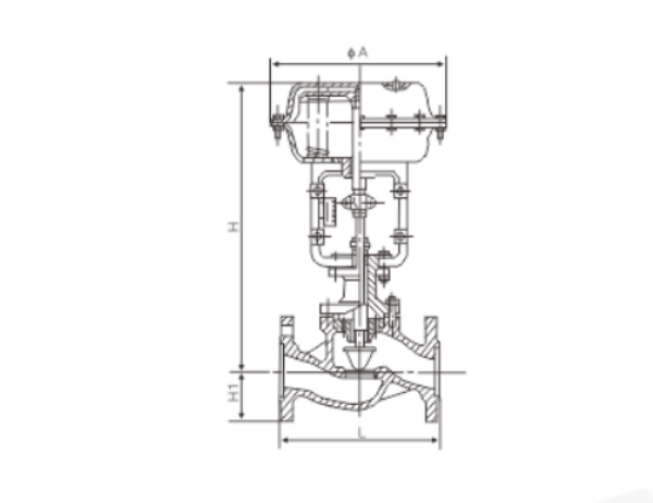
Overall Dimensions
|
DN
|
L
|
H
|
H1
|
Weight (kg)
|
φA
|
|||||||
|---|---|---|---|---|---|---|---|---|---|---|---|---|
|
PN16
|
PN40
|
PN64
|
Standard
|
High temperature
|
PN6
|
PN16
|
PN40
|
PN64
|
PN6, PN16
|
PN40, PN64
|
||
| 25 | 185 | 197 | 210 | 410 | 560 | 50 | 57 | 70 | 20 | 24 | 285 | |
| 40 | 222 | 235 | 251 | 455 | 620 | 65 | 75 | 85 | 26 | 35 | ||
| 50 | 254 | 267 | 286 | 457 | 627 | 70 | 82 | 90 | 30 | 40 | ||
| 65 | 276 | 292 | 311 | 610 | 790 | 80 | 92 | 100 | 47 | 66 | 360 | |
| 80 | 298 | 317 | 337 | 622 | 807 | 95 | 100 | 107 | 55 | 78 | ||
| 100 | 352 | 368 | 394 | 640 | 850 | 105 | 110 | 117 | 125 | 65 | 99 | |
| 150 | 451 | 473 | 508 | 870 | 1130 | 132 | 142 | 150 | 172 | 130 | 160 | 470 |
| 200 | 600 | 650 | 890 | 1150 | 160 | 170 | 187 | 207 | 175 | 250 | ||
| 250 | 730 | 775 | 1203 | 1523 | 187 | 202 | 225 | 235 | 350 | 470 | 580 | |
| 300 | 850 | 900 | 1234 | 1554 | 220 | 230 | 257 | 265 | 500 | 660 | ||
Main Parts Materials
|
Part Name
|
Material
|
Temperature Range
|
|---|---|---|
| Valve Body & Upper Bonnet | HT200 | -20 ~ 200°C |
| ZG230-450 | -40 ~ 450°C | |
| ZG1Cr18Ni9Ti | -250 ~ 550°C | |
| ZG0Cr18Ni12Mo2Ti | -40 ~ 600°C | |
| Plug & Seat | 1Cr18Ni9 | -250 ~ 550°C |
| 0Cr18Ni12Mo2Ti | -250 ~ 550°C | |
| Packing | PTFE | -40 ~ 200°C |
| Diaphragm | Nitrile rubber reinforced with polyester fabric | |
| Compression Spring | 60Si2Mn | |
| Diaphragm Cover | A3 |




 No products in the cart.