


Overview
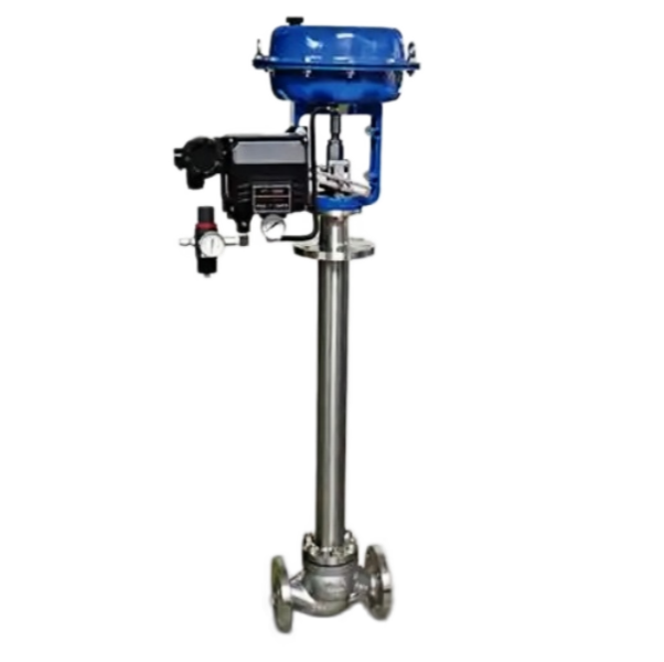
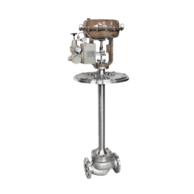
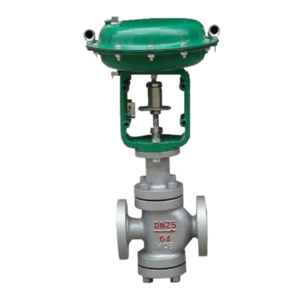
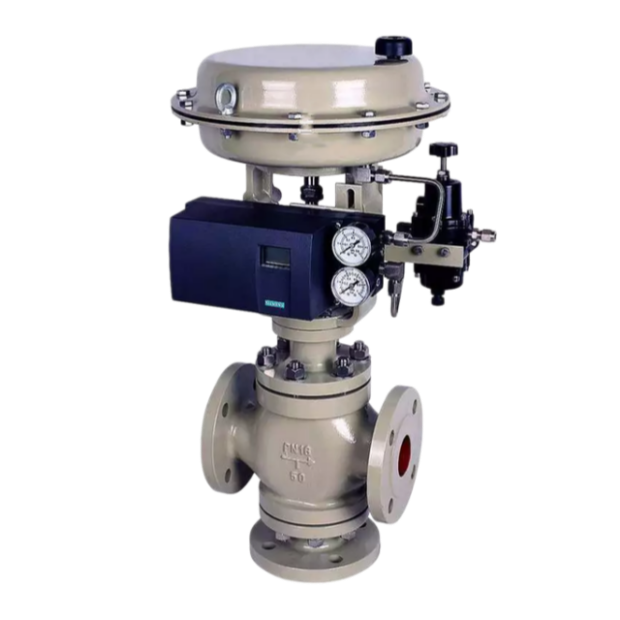
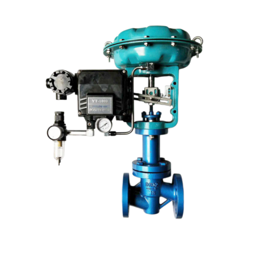
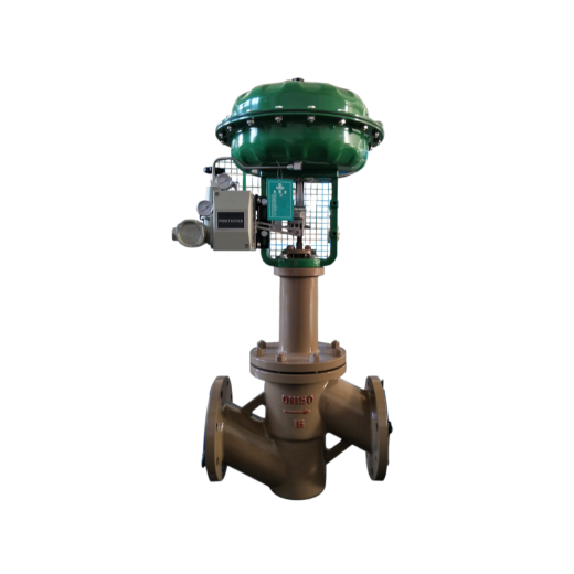
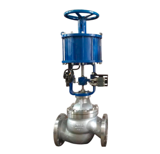
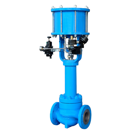
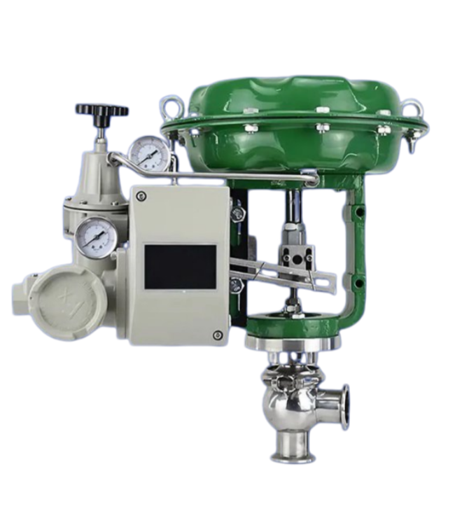
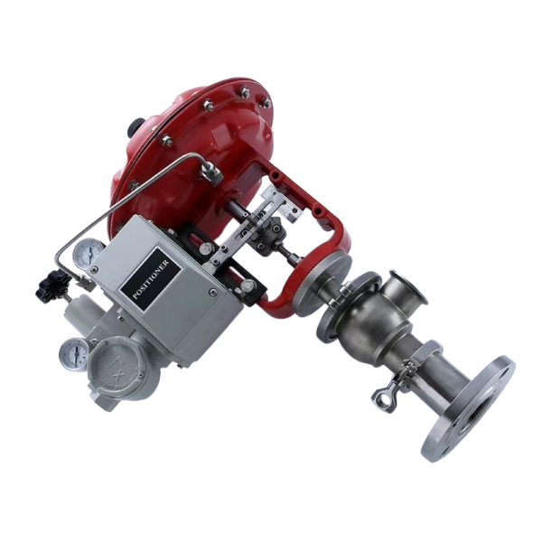
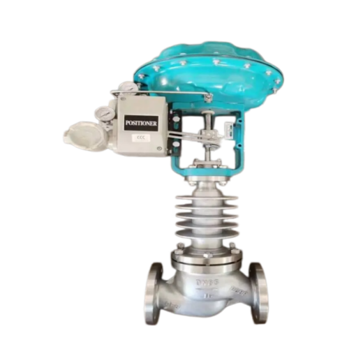
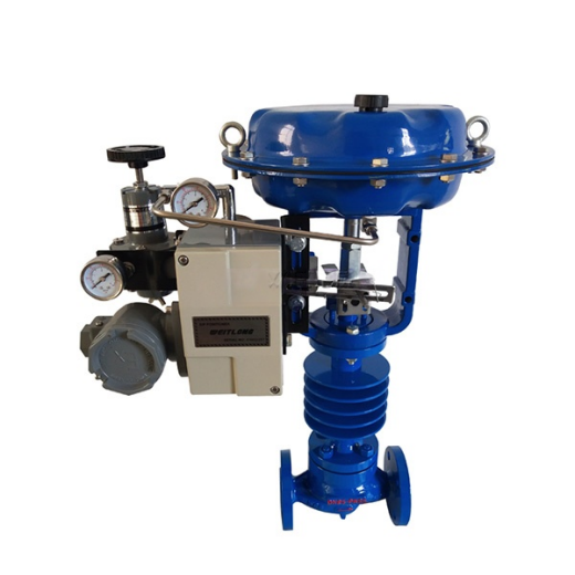
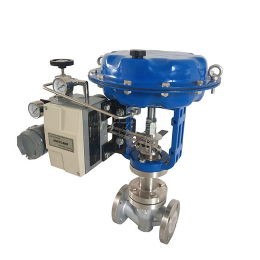
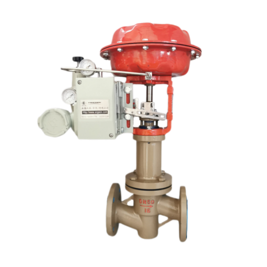
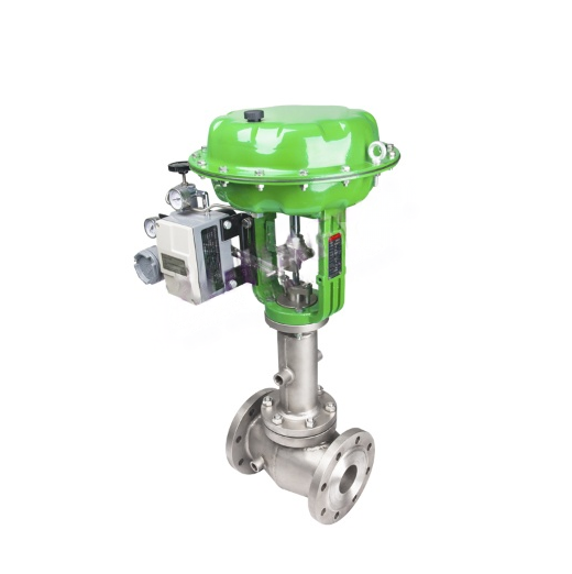
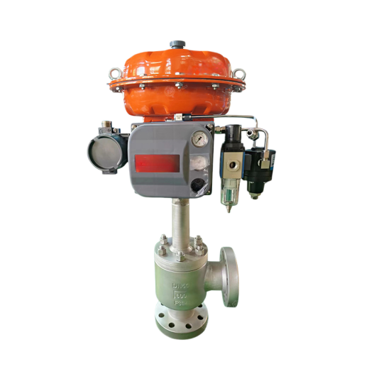
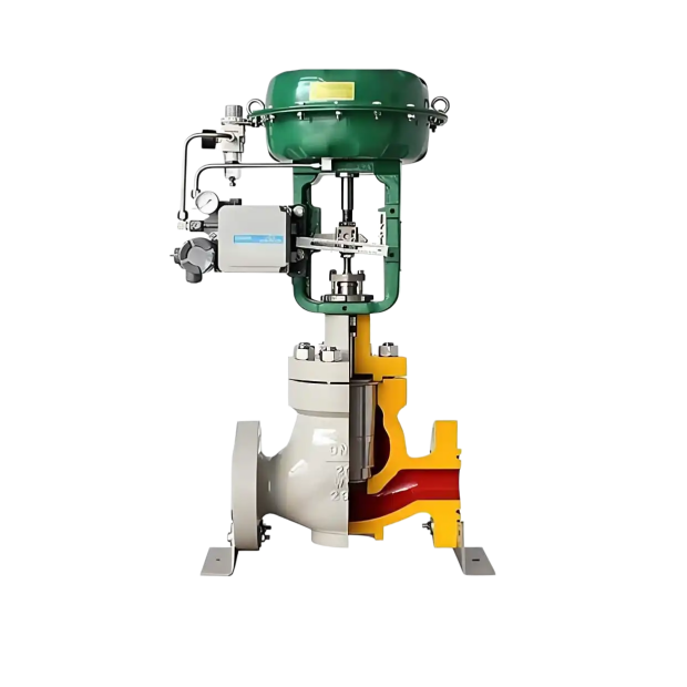
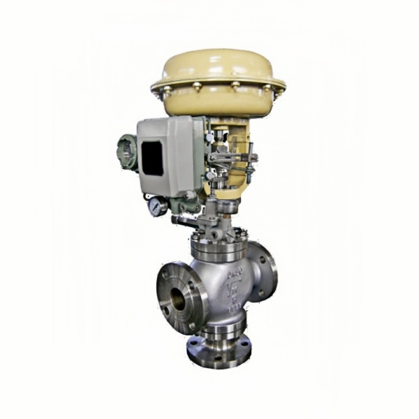
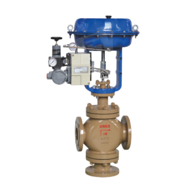
ZJHP Pneumatic Diaphragm Single-Seated Control Valve is a widely used final control element in automatic control systems, consisting of a pneumatic diaphragm actuator and a low-flow-resistance control valve. The single-seated valve is suitable for applications with strict leakage requirements, low differential pressure across the valve, and viscous media or media containing fibers. The double-seated valve features low unbalanced force, large allowable differential pressure and high flow capacity, suitable for applications without strict leakage requirements. The cage valve features good stability, low vibration, low noise and low temperature sensitivity, suitable for applications with relatively large differential pressure and no strict leakage requirements.
Performance Specifications
|
Item
|
Index Value
|
|
|---|---|---|
| Basic Error (%) | Without positioner | ±5.0 |
| With positioner | ±1.0 | |
| Hysteresis (%) | Without positioner | 3.0 |
| With positioner | 1.0 | |
| Dead Band (%) | Without positioner | 3.0 |
| With positioner | 0.4 | |
| Allowable Leakage (L/h) | 1×10⁻³ × rated flow capacity | |
Specifications and Technical Parameters
|
Nominal Diameter (mm)
|
20
|
25
|
40
|
50
|
65
|
80
|
100
|
150
|
200
|
250
|
300
|
350
|
400
|
|||||||
|---|---|---|---|---|---|---|---|---|---|---|---|---|---|---|---|---|---|---|---|---|
|
Seat Diameter (mm)
|
10 | 12 | 15 | 20 | 25 | 32 | 40 | 50 | 65 | 80 | 100 | 125 | 150 | 200 | 250 | 300 | Custom sizes available on request | |||
| Rated Flow Coefficient Kv | Linear | 1.8 | 2.8 | 4.4 | 6.9 | 11 | 17.6 | 27.5 | 44 | 69 | 110 | 176 | 275 | 440 | 690 | 1000 | 1600 | |||
| Equal Percentage | 1.6 | 2.5 | 4 | 6.3 | 10 | 16 | 25 | 40 | 63 | 100 | 160 | 250 | 400 | 630 | 900 | 1440 | ||||
| Nominal Pressure (MPa) | 0.6 1.6 4.0 6.4 | |||||||||||||||||||
| Stroke (mm) | 10 | 16 | 25 | 40 | 60 | 100 | ||||||||||||||
| Flow Characteristic | Linear, equal percentage, quick-open | |||||||||||||||||||
| Media Temperature (°C) | -15 ~ 200 (normal temperature type), -40 ~ +250, -40 ~ +450 (medium temperature type), -100 ~ +200 (low temperature type) | |||||||||||||||||||
| Flange Dimensions | Cast iron flange dimensions per JB78; cast steel flange dimensions per JB79 | |||||||||||||||||||
| Flange Type | Conforms to JB78-59 and JB79-59 standards; can be manufactured to JB/79.1-94, JB/79.2-94, ANSI, JIS, DIN and other standards upon order | |||||||||||||||||||
| Body Material | PN (MPa) | 0.6, 1.6 | WCB(ZG230-450) CF3CF8 CF8M | |||||||||||||||||
| 4.0, 6.4 | WCB(ZG230-450), ZG1Cr18Ni9Ti, ZG0Cr18Ni12Mo2Ti CF8 CF8M | |||||||||||||||||||
| Body Type | Straight-through single-seated cast spherical valve | |||||||||||||||||||
| Plug Material | 1Cr18Ni9, 0Cr18Ni12Mo2Ti CF8 CF8M | |||||||||||||||||||
| Bonnet Type | Plain (normal temperature type), finned (medium temperature type), low temperature type | |||||||||||||||||||
| Available Accessories | Positioner, handwheel, electric/pneumatic converter, air filter regulator | |||||||||||||||||||
| Rangeability R | 30:1 | |||||||||||||||||||
| Air Supply Connection | M16×1.5 | |||||||||||||||||||
Actuator Technical Parameters
|
Model
|
ZHA(B)-1
|
ZHA(B)-2
|
ZHA(B)-3
|
ZHA(B)-4
|
ZHA(B)-5
|
ZHA(B)-6
|
|---|---|---|---|---|---|---|
| Effective Area (cm²) | 200 | 280 | 400 | 630 | 1000 | 1600 |
| Stroke (mm) | 10 | 16 | 25 | 40 | 60 | 100 |
| Spring Range (kPa) | 20 ~ 100 (standard); 40 ~ 200; 80 ~ 240; 20 ~ 60; 60 ~ 100 | |||||
Allowable Differential Pressure
|
Supply Pressure (MPa)
|
Spring Pressure (kPa)
|
Nominal Diameter
|
20
|
20
|
20
|
20
|
25
|
32
|
40
|
50
|
65
|
80
|
100
|
125
|
150
|
200
|
250
|
300
|
|---|---|---|---|---|---|---|---|---|---|---|---|---|---|---|---|---|---|---|
|
Seat Diameter
|
10 | 12 | 15 | 20 | 25 | 32 | 40 | 50 | 65 | 80 | 100 | 125 | 150 | 200 | 250 | 300 | ||
| 0.14 | 20-100 | Allowable Differential Pressure (MPa) | 5.3 | 3.7 | 2.3 | 1.3 | 0.8 | 0.5 | 0.5 | 0.3 | 0.25 | 0.2 | 0.12 | 0.12 | 0.08 | 0.05 | 0.05 | 0.035 |
| 0.24 | 40-200 | 6.4 | 6.4 | 5.5 | 3.1 | 1.8 | 1.2 | 1.1 | 0.7 | 0.65 | 0.45 | 0.18 | 0.18 | 0.10 | 0.10 | 0.10 | 0.07 |
Overall Dimensions
|
DN
|
D
|
PN (MPa)
|
H
|
H1
|
|||
|---|---|---|---|---|---|---|---|
|
1.6
|
4.0
|
6.4
|
Normal Temperature Type
|
Medium Temperature Type
|
|||
| 25 | 280 | 185 | 190 | 200 | 685 | 835 | 115 |
| 32 | 280 | 200 | 210 | 210 | 696 | 847 | 120 |
| 40 | 325 | 220 | 230 | 235 | 754 | 905 | 130 |
| 50 | 325 | 250 | 255 | 265 | 784 | 935 | 145 |
| 65 | 410 | 275 | 285 | 295 | 1065 | 1219 | 180 |
| 80 | 410 | 300 | 310 | 320 | 1076 | 1239 | 195 |
| 100 | 410 | 350 | 355 | 370 | 1085 | 1248 | 200 |
| 125 | 495 | 410 | 425 | 440 | 1286 | 1498 | 245 |
| 150 | 495 | 450 | 460 | 475 | 1306 | 1518 | 255 |
| 200 | 495 | 550 | 560 | 570 | 1381 | 1593 | 275 |
| 250 | 620 | 670 | 740 | 752 | 1455 | 1645 | 380 |
| 300 | 620 | 770 | 803 | 819 | 1510 | 1690 | 430 |
Main Parts Materials and Temperature Range
|
Part Name
|
Material
|
Temperature Range
|
|---|---|---|
| Valve Body & Upper Bonnet | HT200 | -20 ~ 200°C |
| ZG230-450 | -40 ~ 450°C | |
| ZG1Cr18Ni9Ti | -250 ~ 550°C | |
| Plug, Seat & Stem | 1Cr18Ni9 | -250 ~ 550°C |
| Upper & Lower Diaphragm Plates | A3 steel plate | |
| Yoke & Top Cover | HT200 | |
| Compression Spring | 60Si2Mn | |
| Corrugated Diaphragm | 5806 rubber with 480D nylon 66 mesh fabric | |
| Packing | PTFE | -40 ~ 200°C |
| Carbon Fiber | -120 ~ 350°C | |
| Flexible Graphite | -40 ~ 600°C |



 No products in the cart.