


Overview
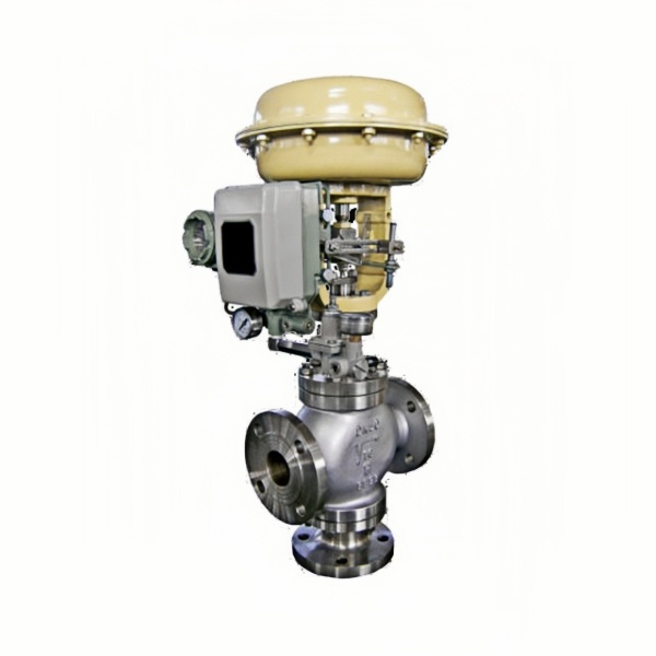
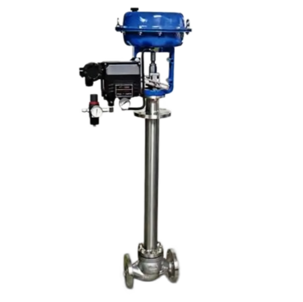
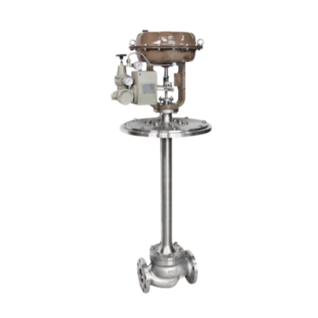
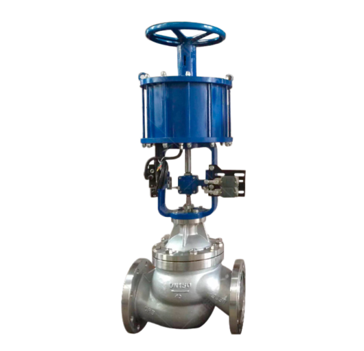
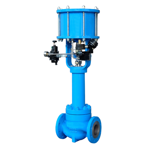
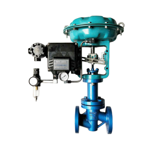
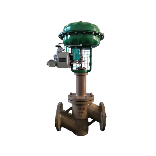
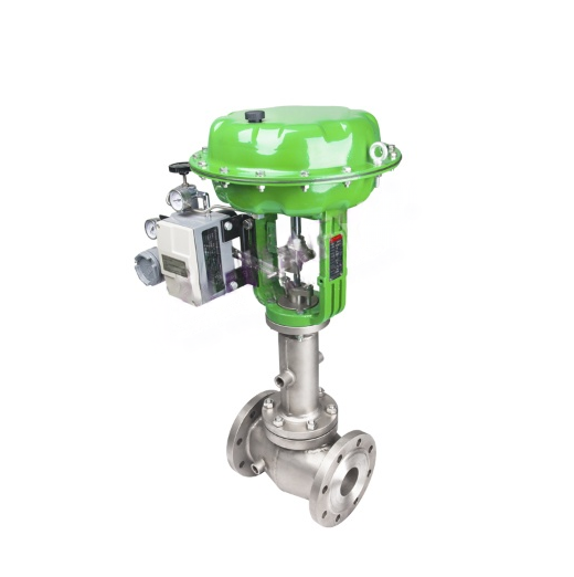
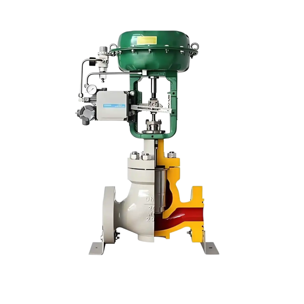
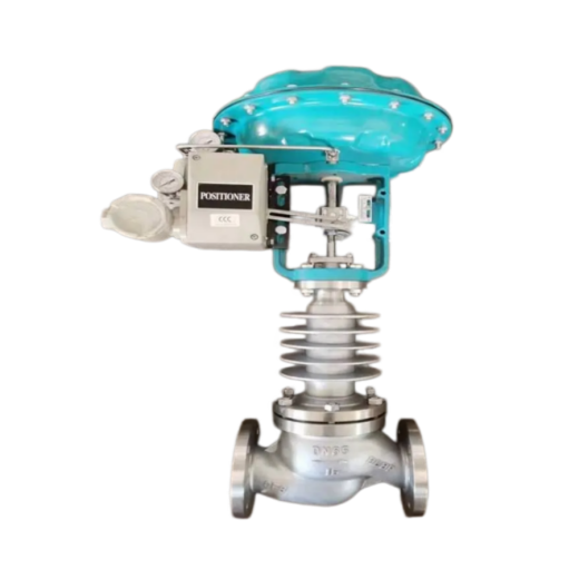
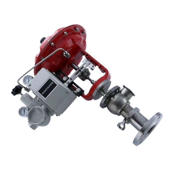
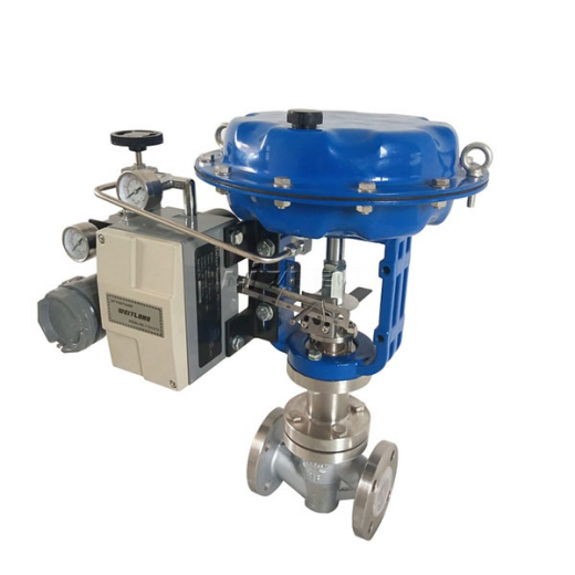
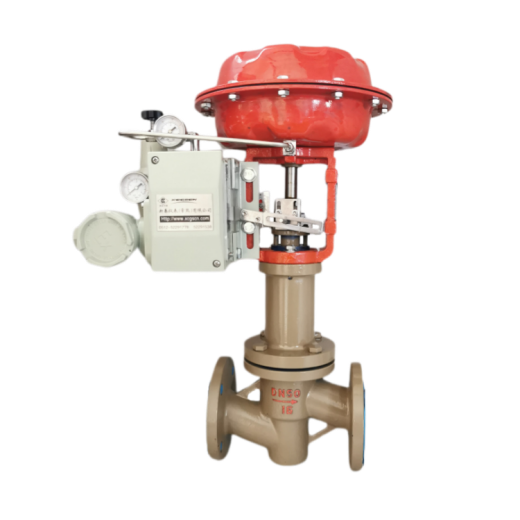
ZMAN-16D pneumatic cryogenic double-seat control valve is a derivative of single-seat and double-seat control valves. Unlike valves used at normal temperature, it features a long-neck type upper bonnet that keeps the packing at ambient temperature. It is suitable for regulating cryogenic media at -60 ~ -250°C, such as liquid oxygen and liquid nitrogen. To ensure regulation accuracy, a positioner must be used.
Structure Principle
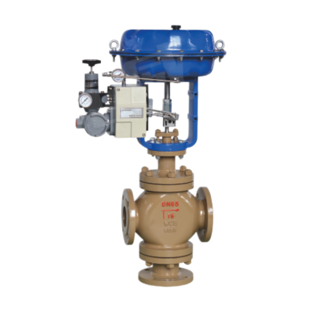
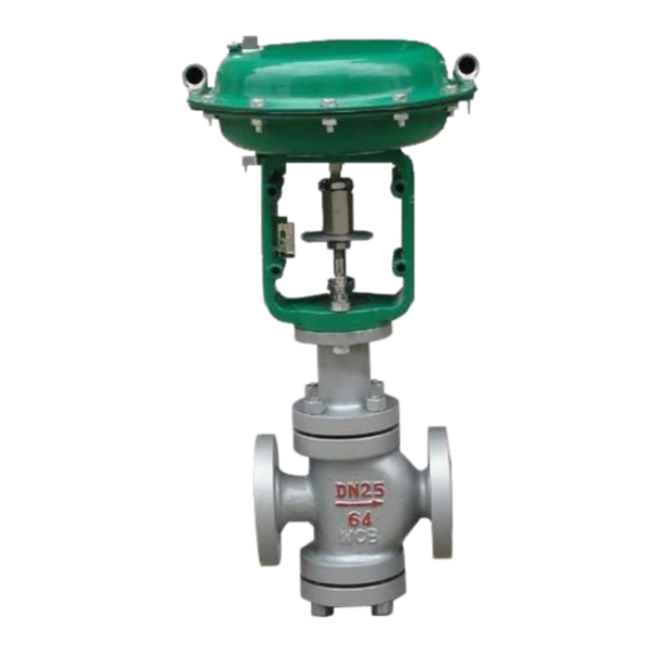
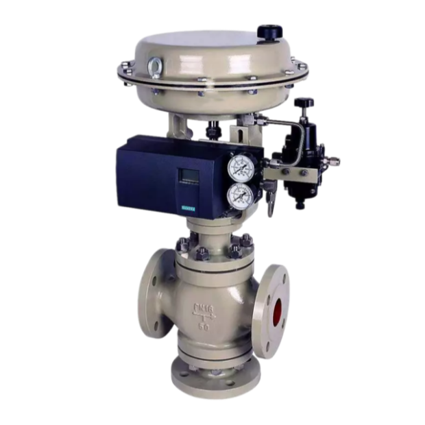
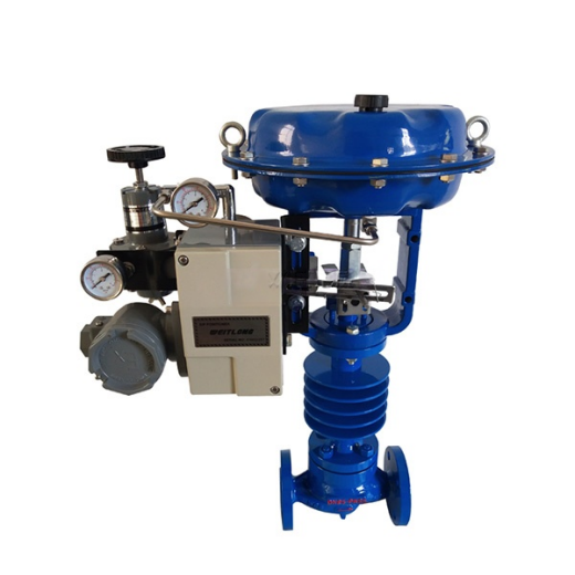
The pneumatic cryogenic control valve consists of a pneumatic diaphragm actuator and a cryogenic-resistant single-seat or double-seat valve body. The signal pressure from the controller enters the air chamber of the pneumatic diaphragm actuator to produce thrust, which drives the valve plug through connecting rods. The change of the plug position varies the flow area of the valve, thereby regulating the medium flow rate.
Technical Parameters
| Nominal Diameter DN |
Single-seat
|
20
|
25
|
32
|
40
|
50
|
65
|
80
|
100
|
125
|
150
|
200
|
|||||||||
|---|---|---|---|---|---|---|---|---|---|---|---|---|---|---|---|---|---|---|---|---|---|
| Double-seat | 25 | 32 | 40 | 50 | 65 | 80 | 100 | 125 | 150 | 200 | |||||||||||
| Rated Flow Coefficient Kv | Single-seat | 0.08 | 0.12 | 0.20 | 0.32 | 0.50 | 0.80 | 1.2 | 2.0 | 3.2 | 5.0 | 8 | 12 | 20 | 32 | 50 | 80 | 120 | 200 | 280 | 450 |
| Double-seat | 10 | 16 | 25 | 40 | 63 | 100 | 160 | 250 | 400 | 630 | |||||||||||
| Flow Characteristic | Linear | Linear; Equal percentage | |||||||||||||||||||
| Actuator Model | ZMA-2 | ZMA-3 | ZMA-4 | ZMA-5 | |||||||||||||||||
| Stroke (mm) | 10 | 10 | 16 | 25 | 40 | 60 | |||||||||||||||
| Action Type | Air-to-close (B), air-to-open (K) | ||||||||||||||||||||
| Spring Pressure Range (kPa) | Standard signal: 20~100; other signals: 40~200; 20~60; 60~100 | ||||||||||||||||||||
Installation Precautions
- The valve shall be installed vertically on a horizontal pipeline. When horizontal or inclined installation is necessary under special circumstances, supports should generally be added. The disc plate installed on the wall of the insulation box should be parallel to the wall of the box.
- It should be installed close to the floor or the floor slab to facilitate maintenance and repair. For valves equipped with a positioner or handwheel mechanism, observation, adjustment and operation should be ensured.
- A bypass pipeline is generally provided so that when the automatic control system fails or during maintenance, manual operation can be switched to without stopping production.
- When a handwheel mechanism is installed, manual operation can be performed without a bypass pipeline, and it can also be used to limit the opening. When not in use, the handwheel mechanism must be returned to its original neutral position to keep the automatic control system operating normally.
- During installation, the medium flow direction should be consistent with the direction indicated on the valve body.
- Before installation, the pipeline should be cleaned of dirt and welding slag. After installation, the valve should be fully opened to clean the pipeline and test the sealing of all connections.
Overall Dimensions
|
Nominal Diameter DN (mm)
|
|
20
|
25
|
32
|
40
|
50
|
65
|
80
|
100
|
125
|
150
|
200
|
|||
|---|---|---|---|---|---|---|---|---|---|---|---|---|---|---|---|
| A | 230 | 280 | 280 | 325 | 410 | 495 | |||||||||
| 135 | 235 | 235 | 255 | 280 | 310 | 345 | 370 | 430 | 470 | 550 | 660 | ||||
| 1 | 160 | 260 | 260 | 285 | 305 | 340 | 375 | 405 | 460 | 525 | 590 | 700 | |||
| 2 | 190 | 290 | 290 | 315 | 335 | 370 | 410 | 440 | 490 | 560 | 630 | 740 | |||
| n- | 6-12 | 8-14 | 8-14 | 8-14 | 8-16 | 10-16 | 10-18 | 12-18 | 16-18 | 20-18 | |||||
| Single-seat | H | L | 120 | 190 | 200 | 210 | 235 | 265 | 295 | 320 | 370 | 440 | 475 | 570 | |
| H1=500 | 862 | 1006 | 1060 | 1066 | 1137 | 1152 | 1377 | 1390 | 1394 | ||||||
| H1=600 | 962 | 1106 | 1160 | 1166 | 1237 | 1252 | 1477 | 1490 | 1494 | ||||||
| H1=700 | 1062 | 1206 | 1260 | 1266 | 1337 | 1352 | 1577 | 1590 | 1594 | 1743 | 1751 | 1790 | |||
| H1=800 | 1162 | 1306 | 1360 | 1366 | 1437 | 1452 | 1677 | 1690 | 1694 | 1843 | 1851 | 1890 | |||
| H1=900 | 1262 | 1406 | 1460 | 1466 | 1537 | 1552 | 1777 | 1790 | 1794 | 1943 | 1951 | 1990 | |||
| H1=1000 | 1362 | 1506 | 1560 | 1566 | 1637 | 1652 | 1877 | 1890 | 1894 | 2043 | 2051 | 2090 | |||
| H1=1100 | 2143 | 2150 | 2190 | ||||||||||||
| H1=1200 | 2243 | 2250 | 2290 | ||||||||||||
| H2 | 32 | 58 | 112 | 118 | 129 | 144 | 178 | 191 | 195 | 243 | 251 | 290 | |||
| Double-seat | H | L | 200 | 210 | 235 | 265 | 295 | 320 | 370 | 440 | 475 | 570 | |||
| H1=500 | 1065 | 1068 | 1147 | 1152 | 1387 | 1407 | 1419 | ||||||||
| H1=600 | 1165 | 1168 | 1247 | 1252 | 1487 | 1507 | 1519 | ||||||||
| H1=700 | 1265 | 1268 | 1347 | 1352 | 1587 | 1607 | 1619 | 1768 | 1778 | 1820 | |||||
| H1=800 | 1365 | 1368 | 1447 | 1452 | 1687 | 1607 | 1719 | 1868 | 1878 | 1920 | |||||
| H1=900 | 1465 | 1468 | 1547 | 1552 | 1787 | 1807 | 1819 | 1968 | 1978 | 2020 | |||||
| H1=1000 | 1565 | 1568 | 1647 | 1652 | 1887 | 1907 | 1919 | 2068 | 2078 | 2120 | |||||
| H1=1100 | 2168 | 2178 | 2220 | ||||||||||||
| H1=1200 | 2268 | 2278 | 2320 | ||||||||||||
| H2 | 117 | 120 | 139 | 144 | 188 | 208 | 208 | 268 | 278 | 320 | |||||



 No products in the cart.