
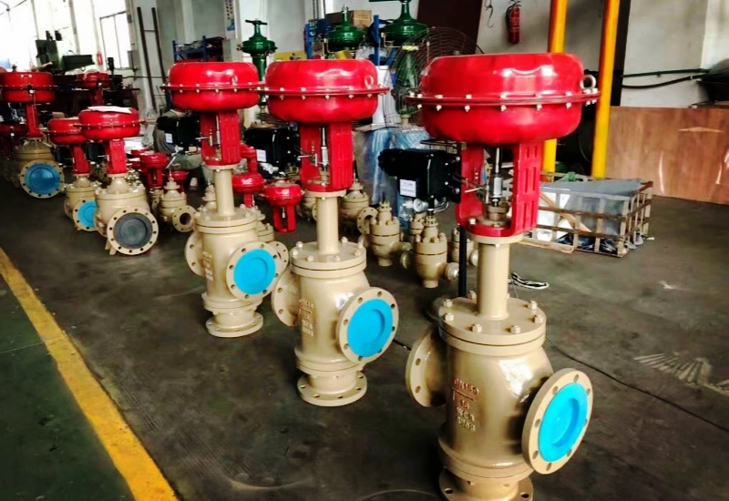
Splitting and mixing of media are common process control requirements in industrial piping systems across the petrochemical, HVAC, pharmaceutical and food, and power industries. Heat exchanger bypass temperature control, heat-medium switching in reactor jackets, and media alternation in CIP cleaning lines all call for a control valve that can precisely distribute or mix media between multiple flow paths.
The pneumatic three-way control valve is a professional solution designed for exactly such duties. It integrates three port connections in a single valve body and is driven by a pneumatic actuator, providing continuous proportional regulation of two media streams, diverging (one inlet, two outlets) or converging (two inlets, one outlet). Compared with the conventional arrangement of two separate single-seat valves, the three-way control valve offers significant advantages in space occupation, piping complexity and control consistency.
This article systematically explains the construction, working principle, technical parameters, selection points, installation and maintenance of the pneumatic three-way control valve, providing a practical reference for the design of industrial piping control systems.
Product Overview
What is a pneumatic three-way control valve?
A pneumatic three-way control valve is a control valve with three pipe connections, consisting of a three-way valve body and a pneumatic actuator (diaphragm or piston type). It receives standard pneumatic signals from the control system (20-100 kPa / 40-200 kPa) or electrical signals (4-20 mA) converted by a positioner, positions the plug inside the body, and thereby changes the flow area between the three ports to achieve proportional diverging or converging of the media.
Core difference between diverging and converging types
Three-way control valves are divided into two categories by function. The internal flow path design and plug construction differ between the two types, and they cannot be interchanged:
| Type | Flow Path | Typical Application | Plug Action Direction |
|---|---|---|---|
| Diverging type (three-way diverging valve) | One inlet (A), two outlets (B, C) | Heat exchanger bypass control; desuperheating of superheated steam | Plug rises to close one outlet and open the other |
| Converging type (three-way converging valve) | Two inlets (A, B), one outlet (C) | Temperature mixing control; media ratio mixing | Plug rises to close one inlet and open the other |
Comparison with the two-single-seat-valve arrangement
| Comparison Dimension | One Three-Way Control Valve | Two Single-Seat Valves |
|---|---|---|
| Installation space | Compact; a single valve body | Twice the space; more piping required |
| Piping complexity | Simple; three ports connected directly | Complex; multiple tees and elbows required |
| Control consistency | Linked single-plug action; synchronized ratio | Two independently controlled valves; coordination required |
| Cost | Higher single-valve purchase cost | Total procurement cost may be higher (including fittings) |
| Maintenance | One body; fewer maintenance points | Two bodies; twice the maintenance points |
| Leakage risk | One sealing surface | Two sealing surfaces |
Diverging and Converging Service Analysis
Diverging service scenarios
The core requirement of diverging control is to split one incoming stream proportionally between two downstream lines.
Typical scenario 1: Heat exchanger bypass temperature control. In a heat exchanger inlet/outlet bypass system, the three-way diverging valve is installed upstream of the heat exchanger inlet. One stream passes through the heat exchanger to be heated or cooled, while the other bypasses the exchanger. By adjusting the flow ratio of the two streams, the mixed outlet temperature is held precisely at the setpoint. This is the most classic application of the three-way diverging valve.
Typical scenario 2: Superheated steam desuperheating. In steam desuperheating systems, superheated steam is split into two paths: one through the desuperheater to be cooled, and one through a bypass to remain at high temperature. The three-way diverging valve adjusts the ratio of the two paths to deliver steam at the required temperature.
Converging service scenarios
The core requirement of converging control is to mix two streams of different states (temperature, composition or pressure) proportionally and deliver them downstream.
Typical scenario 1: Temperature mixing control. Hot and cold water are mixed through a three-way converging valve to provide constant-temperature supply at the outlet. This is very common in HVAC systems, replacing the conventional arrangement of an electric two-way valve plus bypass pipe, and gives higher control accuracy.
Typical scenario 2: Media ratio mixing. In the pharmaceutical and food industries, two liquids of different concentrations are mixed proportionally through a three-way converging valve to achieve precise formulation control.
Effect of flow characteristic on control performance
Two flow characteristic families are used in the design of three-way control valves:
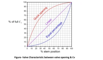
- Linear characteristic: for constant pressure drop systems; plug travel is proportional to flow, giving stable control.
- Equal percentage characteristic: for varying pressure drop systems; low gain at small openings and high gain at large openings, adapting to wide regulation ranges.
For three-way valves, the linear characteristic is recommended. In diverging or converging duty the total flow through both paths should remain essentially constant (depending on the plug design), and the linear characteristic makes the transition between the two paths smoother.
Features and Advantages
Core advantages
- One body for both diverging and converging service: the same body can be switched between diverging and converging by replacing the plug assembly, reducing spare parts inventory.
- High positioning accuracy: the matched intelligent positioner provides control accuracy up to ±0.5 % with a fast response.
- Lapped dual sealing surfaces: the plug and seat sealing surfaces are lapped in pairs, achieving a leakage class of Class IV or better.
- All-stainless-steel body: the standard body material is CF8M (316 stainless steel), offering excellent corrosion resistance for a wide range of industrial media.
- Modular pneumatic actuator: diaphragm or piston type selectable, with output torque covering the full DN15-DN250 series.
- Low-emission packing system: meets the ISO 15848-1 low-leakage standard, ensuring environmental compliance.
Reliability design
- Stable plug guiding structure with strong resistance to side loads; not prone to sticking.
- Spring-return actuator as standard; the valve returns automatically to its fail position on loss of air or signal (FC/FO selectable).
- Optimized flow path design reduces dead zones and deposit accumulation in the body.
- Internal components are sourced from reliable brands to ensure overall quality.
Intelligent control options
- Smart positioner supporting HART, Profibus PA and Foundation Fieldbus communication.
- Self-diagnosis: real-time monitoring of valve stroke, friction changes and air supply pressure.
- One-touch auto calibration: no manual stroke and zero setting required.
- Data logging: operation logs are stored for fault analysis and predictive maintenance.
Technical Parameters
Basic technical parameters
| Parameter | Typical Range |
|---|---|
| Nominal diameter (DN) | DN15 – DN250 |
| Nominal pressure (PN) | PN16 / PN25 / PN40 (ANSI 150LB / 300LB) |
| Connection type | Flanged (RF / RTJ) |
| Flow characteristic | Linear / equal percentage |
| Rangeability | 30:1 |
| Leakage class | Class IV / Class VI (soft seat) |
| Body material | WCB / CF8 / CF8M / CF3M |
| Plug material | 304 / 316 / 316L + Stellite |
| Working temperature | -40 °C to +450 °C |
| Pneumatic actuator | Diaphragm / piston (spring return optional) |
| Input signal | 4-20 mA / 20-100 kPa |
| Air supply pressure | 0.4-0.7 MPa |
Typical Cv values
| Nominal Diameter | Cv (Converging) | Cv (Diverging) |
|---|---|---|
| DN15 | 4.0 | 3.5 |
| DN25 | 12 | 10 |
| DN50 | 45 | 40 |
| DN80 | 100 | 90 |
| DN100 | 170 | 155 |
| DN150 | 380 | 350 |
Selection Guide
Four-step selection method
Step 1: Determine the functional type. Is diverging (one inlet, two outlets) or converging (two inlets, one outlet) required? Do both outlets/inlets participate in regulation, or is one path simply an on-off bypass?
Step 2: Determine the process parameters. Media type, temperature and pressure; total flow and the flow split ratio between the two branches; allowable pressure drop range; and whether the media contains particles or tends to crystallize.
Step 3: Calculate the Cv value and select the size. Calculate the required Cv from the maximum flow and allowable pressure drop, compare it against the Cv table for the closest size, and verify that the rated Cv provides a margin of 130 % of the maximum flow.
Step 4: Check the actuator. Calculate the unbalanced force acting on the plug at the maximum differential pressure, select a pneumatic actuator output torque with a 30 % safety margin, and confirm that the air supply pressure matches the actuator.
Common selection mistakes
Mistake 1: Using a diverging valve for converging duty. The diverging and converging types have different plug constructions. Reverse use causes seal failure and severely deviating flow characteristics. Never mix the two.
Mistake 2: Ignoring the pressure drop characteristics of the three-way valve. The pressure drop behavior of a three-way valve is closely related to the resistance of both piping paths. If the bypass line resistance is far lower than the heat exchanger side, most of the media flows through the bypass even with the valve fully open. The resistance of the two paths must be balanced during piping design.
Mistake 3: Oversizing the valve. An oversized three-way valve operates at small openings for long periods, reducing regulation accuracy and causing erosion wear. Select the size by the normal flow, not by the pipe size.
Installation and Maintenance
Installation notes
Confirm the installation direction.
- Diverging type: connect the inlet (A) to the incoming flow line, and the two outlets (B, C) to the heat exchanger and the bypass respectively.
- Converging type: connect the two inlets (A, B) to the heat source and the cold source, and the outlet (C) to the mixed downstream line.
- Note the flow direction arrow marked on the valve body. Never reverse the connection.
Piping layout.
- Keep a straight run of at least 10D upstream of the valve and 5D downstream.
- Install a bypass system where possible to allow online maintenance.
- Locate the three-way valve close to the heat user to reduce temperature loss in the mixed line.
- Install a filter regulator and air lubricator on the air supply line.
Air supply connection.
- Compressed air quality must comply with ISO 8573-1 (oil, water and dust levels).
- Match the air tube inner diameter to the actuator port; the total header length should not exceed 60 m.
- Protect the solenoid valve and positioner air ports from dust and moisture.
Commissioning steps
- Operate the actuator handwheel manually and check the plug over its full stroke; confirm there is no sticking.
- Connect the air supply and check that the actuator action direction matches the signal relationship.
- Carry out positioner auto calibration: perform one-touch stroke setting as per the positioner manual.
- Zero check: a 4 mA signal should correspond to one path fully open and the other fully closed.
- Span check: a 20 mA signal should switch the valve to the opposite state.
- Midpoint check: at a 12 mA signal, both paths should each be 50 % open; verify the flow is balanced.
- Joint test with the DCS/PLC.
Routine maintenance
| Maintenance Item | Period | Operation |
|---|---|---|
| Visual inspection | Weekly | Check the valve body and air connections for leakage and abnormal vibration |
| Valve position check | Monthly | Give a 50 % signal via the DCS and verify the actual valve opening on site |
| Air supply system | Monthly | Check the filter regulator and drain accumulated water |
| Packing tightening | Quarterly | Tighten the packing gland moderately (torque per the manual) |
| Actuator servicing | Semi-annually | Inspect the diaphragm; lubricate the cylinder |
| Seal test | Annually | Check wear of the plug and seat sealing surfaces |
Common faults and troubleshooting
| Fault | Possible Cause | Solution |
|---|---|---|
| Valve does not act | Air supply interrupted / positioner fault | Check the air supply pressure; test the actuator manually |
| Stroke switching incomplete | Insufficient air pressure / spring fatigue | Check the supply pressure; replace the spring |
| Excessive internal leakage | Seal surface wear / debris sticking | Lap the sealing surfaces or replace the plug and seat |
| Flow mismatch between the two paths | Unbalanced piping resistance | Check the piping; add a balancing valve if necessary |
| Noise and vibration | Oversized valve / cavitation | Recheck the sizing; verify whether service conditions have changed |

 No products in the cart.