


Overview
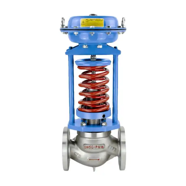
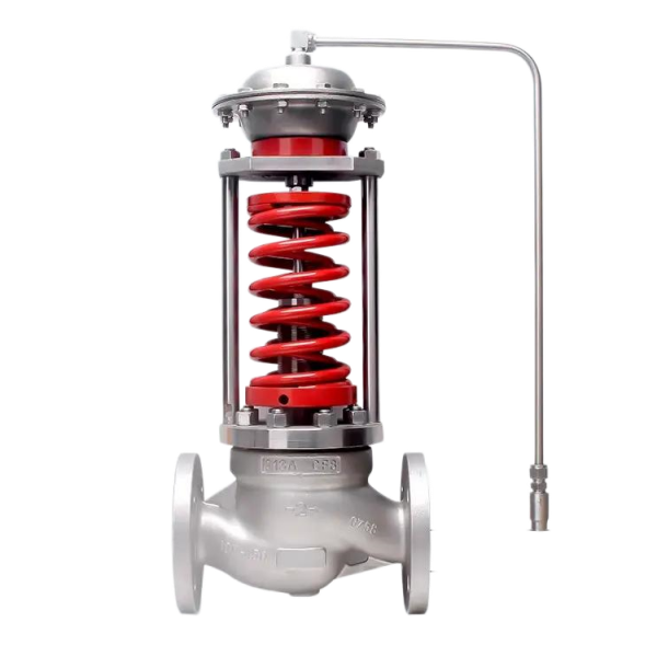
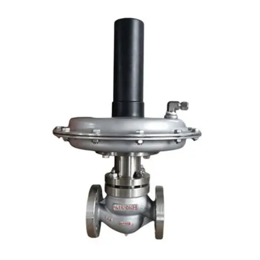
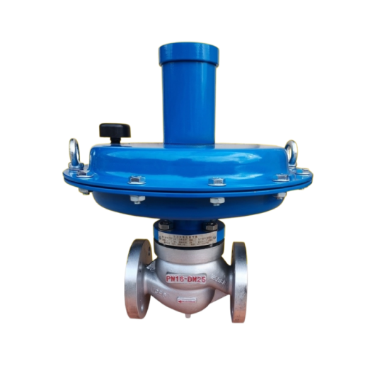
ZZYVP tank blanketing valve, also known as the nitrogen seal valve, is specially designed for gas blanketing protection of large storage tanks. Connection types include internal thread, external thread, flange, welding, butt welding, socket welding, compression fitting and clamp. It is widely used for automatic pressure reduction and stabilization (downstream regulation) or pressure relief and stabilization (upstream regulation) of gas, liquid and steam media in the petroleum, chemical, power, metallurgical, food, textile, machinery manufacturing and residential building industries, as well as for micro-pressure automatic regulation in applications such as controlling the mixing ratio of two fuel gases in industrial furnace combustion systems, seal oil systems of hydrogen-cooled generator sets, protective gas for petroleum products in process or tank farm storage, and heat-treatment protective atmospheres.
When the blanketing valve opens, if the tank pressure drops slightly below the set point, the diaphragm moves downward in response to the pressure drop and opens the pilot valve. Nitrogen then flows through the orifice plate and the pilot valve outlet into the tank, raising the tank pressure. At the same time, the pressure in the special plug chamber of the pilot valve decreases, and nitrogen flows through the internal passage from the plug chamber into the main valve plug chamber.
In normal operation the valve requires no external energy supply, achieving automatic regulation using the energy of the controlled medium itself. It also features energy saving, a pressure set point that can be adjusted at any time during operation, a quick-opening flow characteristic, sensitive response, good sealing performance, stable medium pressure, high control accuracy and low leakage.
Features
- No external energy supply: suitable for sites without electricity or instrument air; convenient, energy-saving and cost-effective.
- Nitrogen supply and relief pressure set points can be adjusted easily, even during continuous production.
- Large effective area of the pressure-sensing diaphragm with low set spring stiffness: sensitive response and stable operation.
- Packingless design minimizes stem friction, giving rapid response and high control accuracy.
- The nitrogen supply device is pilot-operated, achieving a pressure reduction ratio of up to 100:1 with excellent pressure reduction and control accuracy.
- A breather valve should be installed on the tank roof to ensure tank safety.
- The breather valve serves a safety function only, avoiding the frequent cycling and premature failure common in conventional blanketing devices.
Main Parts Common Materials
| Component | Material |
|---|---|
| Valve Body | ZG230-450, ZG1Cr18Ni9Ti, ZGCr18Ni12Mo2Ti, HT200 |
| Valve Seat & Stem | 1Cr18Ni9Ti, Cr18Ni12Mo2Ti |
| Spring | 60Si2Mn, 1Cr18Ni9Ti, 50CrVA |
| Packing | PTFE, flexible graphite |
| Diaphragm | NBR, EPDM, FKM, oil-resistant rubber, silicone rubber, fluororubber |
| Plug | Metal part: 1Cr18Ni9Ti, Cr18Ni12Mo2Ti; soft-seal part: PTFE, graphite + PTFE |
| Diaphragm Cover | A3 steel, A3 steel coated with PTFE |
Specifications & Technical Parameters
| Nominal Diameter DN (mm) | 15 | 20 | 25 | 32 | 40 | 50 | 65 | 80 | 100 | 125 | 150 | |||||||
| Rated Flow Coefficient Kv | 4.4 | 6.9 | 11 | 17.6 | 27.5 | 44 | 69 | 110 | 176 | 275 | 440 | |||||||
| Pressure Adjustment Range (kPa) | 0.5~70, 20~120, 60~400, 300~700, 500~1000 | |||||||||||||||||
| Nominal Pressure PN (MPa) | 1.6, 4.0 | |||||||||||||||||
| Service Temperature (°C) | 80, 200 | |||||||||||||||||
| Control Accuracy (%) | ≤5 | |||||||||||||||||
| Actuator Diaphragm Effective Area (cm2) | 200 | 280 | 400 | |||||||||||||||
| Allowable Leakage | Hard Seat (L/h) | 10-4 × rated valve capacity | ||||||||||||||||
| Soft Seat (ml/min) | 0.15 | 0.3 | 0.45 | 0.60 | 0.90 | 1.70 | 4.0 | |||||||||||
| Pressure Reduction Ratio (upstream/downstream) | 100~1.25 | |||||||||||||||||
| Flange Standard | GB9113-88 | |||||||||||||||||
Maintenance
- Install the valve so that the stem travel direction and the actuator above the body lie in the same vertical plane. If the valve must be installed with the stem horizontal or inclined to the horizontal, support the actuator so that all valve components remain in their natural state.
- Valves in service should be intact, with all flange and bracket bolts present, threads undamaged and no loosening.
- Avoid or eliminate stress on the blanketing valve, directing stress away from the valve.
- The valve scale should remain complete, accurate and legible; the valve lead seal, caps and pneumatic accessories should be complete and in good condition.
- Valves should be inspected regularly, with dirt removed and rust-preventive oil applied to the surface.
- For valves and accessories used in explosive hazardous areas, check their safe operating condition.
- Maintain the valve in an overall vertical or horizontal position. When shipping long distances, use a sturdy wooden crate.
Notes
- The nitrogen relief valve is normally installed on the tank roof, with its size matching the inlet valve size as applicable.
- The pressure set point of the relief valve should be slightly higher than that of the supply valve, to avoid frequent operation of the supply and relief devices that would waste nitrogen and shorten equipment service life.
- The general nitrogen supply pressure is between 3 × 10⁵ and 10 × 105 Pa.
- The roof breather valve serves a safety function only: it operates when the main valve fails and causes the tank pressure to become too high or too low, and does not operate under normal conditions.


 No products in the cart.