
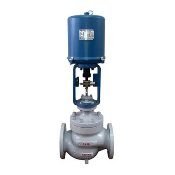
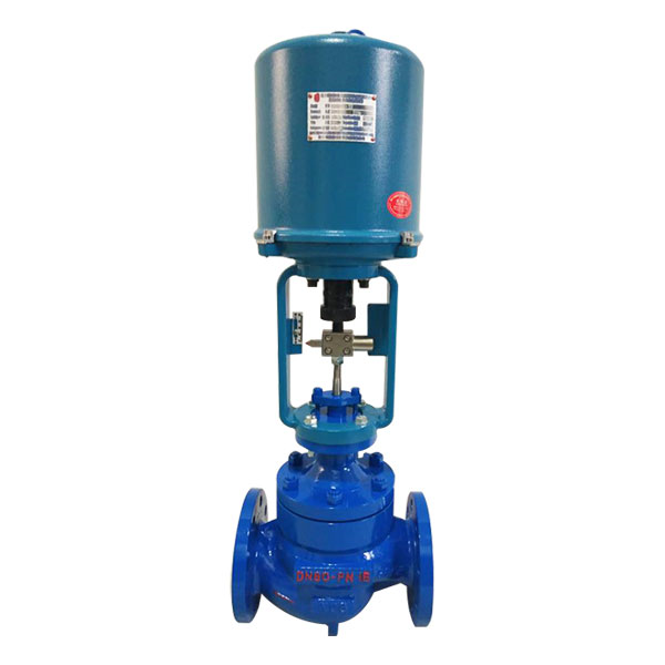
Overview
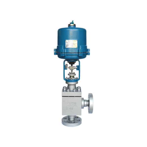
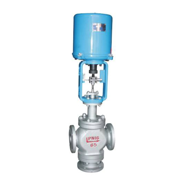
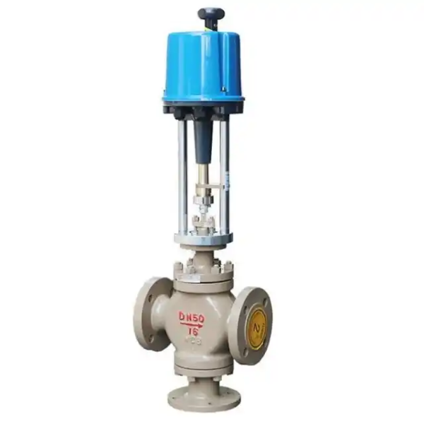
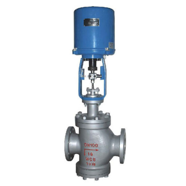
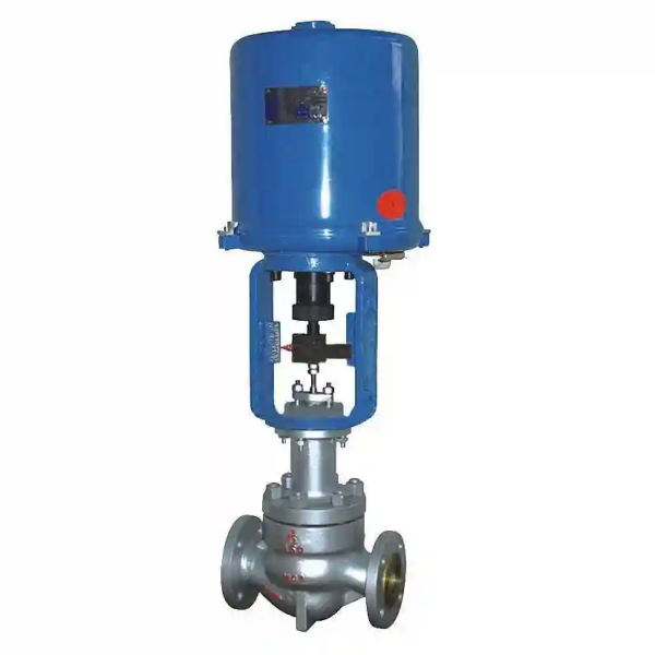
ZDLM electronic electric cage-type control valve consists of a PS series or 3610 series linear-stroke electric actuator and a low-resistance, straight-through, single-seat valve body (actuators of other brands can also be fitted). The electric actuator features an integrated electronic design with a built-in servo amplifier: once the control signal (4-20 mA DC or 1-5 V DC) and power supply are connected, the valve is positioned automatically, providing regulation of process parameters such as pressure, flow rate, liquid level and temperature. It offers quick response, simple wiring, high flow capacity, compact size and high regulating accuracy.
The cage-guided valve provides good stability, is resistant to vibration, offers low noise and low sensitivity to temperature. The single-seal version is suitable for clean media where tight leakage requirements apply and the differential pressure is moderate; the double-seal version suits clean media where leakage requirements are less stringent and the differential pressure is higher; the multi-hole throttling version can be used as a low-noise valve. Widely applied in electric power, metallurgy, chemical, petroleum, environmental protection, light industry and other industries.
Main Technical Parameters
|
Nominal Diameter (mm)
|
25
|
32
|
40
|
50
|
65
|
80
|
100
|
125
|
150
|
200
|
250
|
300
|
|
|---|---|---|---|---|---|---|---|---|---|---|---|---|---|
|
Seat Bore Diameter (mm)
|
26
|
32
|
40
|
50
|
66
|
80
|
100
|
125
|
150
|
200
|
250
|
300
|
|
| Rated Flow Coefficient Kv | Linear | 11 | 17.6 | 27.5 | 44 | 69 | 110 | 176 | 275 | 440 | 690 | 1100 | 1760 |
| Equal % | 10 | 16 | 25 | 40 | 63 | 100 | 160 | 250 | 400 | 630 | 1000 | 1600 | |
| Nominal Pressure (MPa) | 0.6, 1.6, 2.5, 4.0, 6.4 | ||||||||||||
| Stroke (mm) | 16 | 25 | 40 | 60 | 100 | ||||||||
| Flow Characteristics | Linear, equal percentage, quick opening | ||||||||||||
| Working Temperature (°C) | -40 ~ 230 (standard type); finned type 230 ~ 450 (medium temperature type); special order -100 ~ 600 | ||||||||||||
| Flange Dimensions | In accordance with JB78-59, JB79-59, JB/79.1-94, JB, ANSI, JIS, DIN and other standards, manufactured to order | ||||||||||||
| Body Material | WCB (ZG230-450), ZG1Cr18Ni9Ti, ZG0Cr18Ni12Mo2Ti, CF8, CF8M | ||||||||||||
| Trim Material | 1Cr18Ni9, SS304, 0Cr18Ni12Mo2Ti, SS316, ZG1Cr18Ni9Ti | ||||||||||||
| Body Type | Straight-through cage-type cast globe valve | ||||||||||||
| Bonnet Type | Standard (normal temperature), finned (medium temperature), extended neck (low temperature) | ||||||||||||
| Matching Electric Actuator Models | PSL | PSL-202 | PSL-204 | PSL-208 | PSL-312 | PSL-325 | |||||||
| 361L | 361LSA-20 | 361LSB-30 | 361LSB-50 | 361LSC-65 | 361LSC-99 | ||||||||
| Explosion-proof | 361LXA-20 | 361LXB-30 | 361LXB-50 | ||||||||||
Notes: 1. Valves with flange dimensions to ANSI, JPI and other international standards are available; the face-to-face dimension shall be determined as required. 2. For working temperature, nominal pressure or nominal diameter beyond the listed ranges, please contact us for a solution.
Actuator Technical Parameters
|
Model
|
Rated Output Force (N)
|
Speed (mm/s)
|
Technical Parameters
|
||||
|---|---|---|---|---|---|---|---|
|
PSL
|
361L
|
PSL
|
361L
|
PSL
|
361L
|
PSL
|
361L
|
| 201 | 361LSA-08, 361LXA-08 | 1000 | 800, 800 | 0.25 | 4.2, 4.2 | Power supply: AC220V 50Hz; Input signal: DC4-20mA, DC1-5V (shielded cable for signal wiring); Output signal: DC4-20mA; Protection class: IP67; With handwheel | Power supply: AC220V 50Hz; Input signal: DC4-20mA, DC1-5V (shielded cable for signal wiring); Output signal: DC4-20mA; Protection class: equivalent to IP55; Explosion-proof marking: Exd II BT4; With handle |
| 202 | 361LSA-20, 361LXA-20 | 2000 | 2000, 2000 | 0.50 | 2.1, 2.1 | ||
| 204 | 361LSB-30, 361LXB-30 | 4500 | 3000, 3000 | 0.50 | 3.5, 3.5 | ||
| 208 | 361LSB-50, 361LXB-50 | 8000 | 5000, 5000 | 1.00 | 1.7, 1.7 | ||
| 312 | 361LSC-65 | 12000 | 6500 | 0.60 | 2.8 | ||
| 325 | 361LSC-99 | 25000 | 10000 | 1.0 | 2.0 | ||
Performance Specifications
|
Item
|
Value
|
||
|---|---|---|---|
| Basic Error (%) | With 361L: 2.0; with PSL: 0.1 | ||
| Hysteresis (%) | 2.5 | ||
| Dead Band (%) | 1.0 | ||
| Start/End Point Deviation (%) | Signal-to-open | Start point | ±2.5 |
| End point | ±2.5 | ||
| Signal-to-close | Start point | ±2.5 | |
| End point | ±2.5 | ||
| Rangeability | 30:1 | ||
| Rated Stroke Deviation (%) | 2.5 | ||
| Allowable Leakage (L/h) | Single seal: in accordance with JB/T7387-94 Class IV, less than 10-4 of the rated flow capacity; double seal: in accordance with JB/T7387-94 Class III, less than 10-3 of the rated flow capacity | ||
Allowable Differential Pressure
|
Nominal Diameter DN (mm)
|
25
|
40
|
50
|
65
|
80
|
100
|
150
|
200
|
250
|
300
|
|||
|---|---|---|---|---|---|---|---|---|---|---|---|---|---|
|
Seat Bore (mm)
|
25
|
32
|
40
|
50
|
65
|
80
|
100
|
125
|
150
|
200
|
250
|
300
|
|
|
Actuator
|
Allowable Differential Pressure ΔP (MPa)
|
||||||||||||
| With PSL | PSL-202 | 6.4
3.14 |
6.4
1.92 |
6.4
1.23 |
5.1
0.78 |
||||||||
| PSL-204 | 4.31 | 2.76 | 1.76 | 6.4
1.04 |
6.4
0.69 |
5.62
0.44 |
|||||||
| PSL-208 | 1.86 | 1.23 | 0.78 | 6.4
0.50 |
5.31
0.35 |
3.97
0.20 |
|||||||
| PSL-320 | 1.26 | 0.87 | 0.49 | 6.4
0.32 |
4.14
0.22 |
||||||||
| With 361L | 361LSA-20 | 6.4
3.14 |
6.4
1.92 |
6.4
1.23 |
6.4
0.78 |
||||||||
| 361LSB-50 | 6.4
1.16 |
6.4
0.76 |
6.25
0.49 |
||||||||||
| 361LSC-65 | 6.4
0.64 |
4.32
0.41 |
3.23
0.28 |
||||||||||
| 361LSC-99 | 0.63 | 0.44 | 0.25 | 3.31
0.16 |
0.27
0.11 |
||||||||
Note: In each cell, the upper value is the allowable differential pressure for the double-seal version and the lower value for the single-seal version. The actual actuator configuration shall be determined according to the specific process parameters. If the allowable differential pressure is unclear or the maximum working differential pressure exceeds the listed ranges, please contact us.
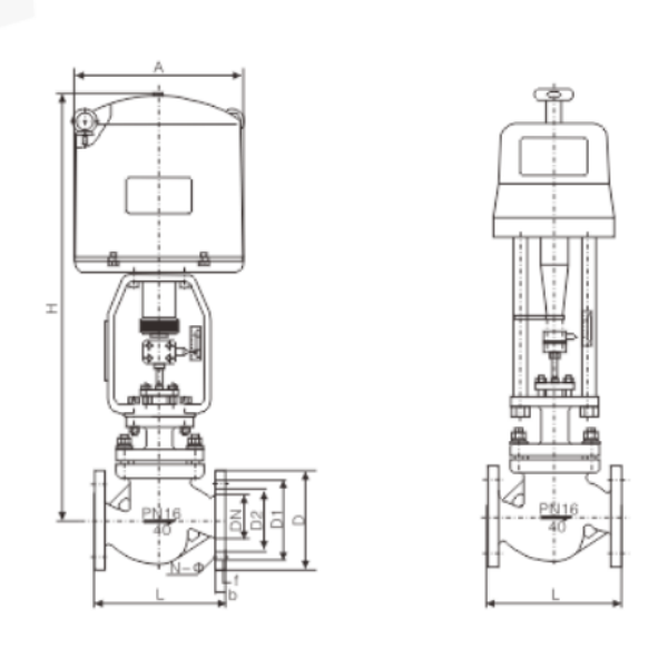
Overall Dimensions
|
DN (mm)
|
25
|
40
|
50
|
65
|
80
|
100
|
150
|
200
|
250
|
300
|
||
|---|---|---|---|---|---|---|---|---|---|---|---|---|
| L (mm) | PN1.6 MPa | 184 | 222 | 254 | 276 | 298 | 352 | 451 | 600 | 720 | 820 | |
| PN4.0 MPa | 197 | 235 | 267 | 292 | 317 | 368 | 473 | 600 | 760 | 850 | ||
| PN6.4 MPa | 210 | 251 | 286 | 311 | 337 | 394 | 508 | 650 | 800 | 870 | ||
| H1 (mm) | 72 | 87 | 92 | 105 | 110 | 127 | 174 | 209 | 300 | 350 | ||
| With PSL | H (mm) | Standard | 750 | 765 | 767 | 845 | 857 | 875 | 1025 | 1045 | 1252 | 1545 |
| Finned | 900 | 930 | 937 | 1025 | 1042 | 1085 | 1285 | 1305 | 1805 | 1825 | ||
| D (mm) | 176 | 225 | ||||||||||
| Weight (kg) | 23.5 | 33.5 | 40.5 | 69 | 84 | 112 | 189 | 262 | 415 | 635 | ||
| With 361L | H (mm) | Standard | 513 | 650 | 652 | 770 | 782 | 800 | 1080 | 1125 | 1345 | 1365 |
| Finned | 663 | 815 | 822 | 950 | 967 | 1010 | 1340 | 1385 | 1625 | 1645 | ||
| D (mm) | 225 | 310 | ||||||||||
| Weight (kg) | 31 | 49 | 56 | 84 | 99 | 127 | 242 | 315 | 463 | 683 | ||


 No products in the cart.