
Overview
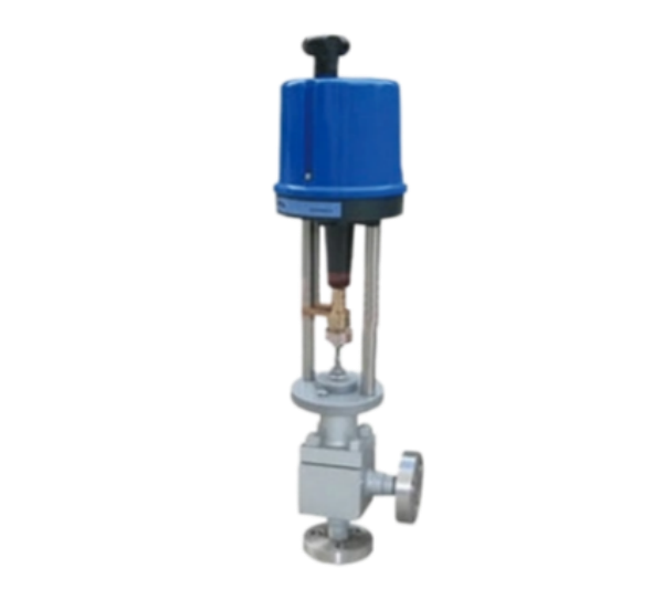
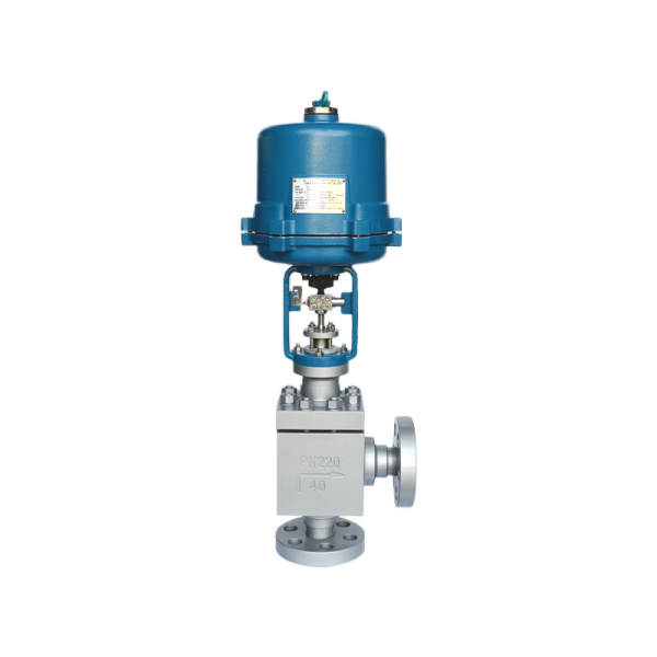
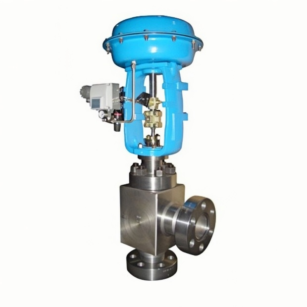
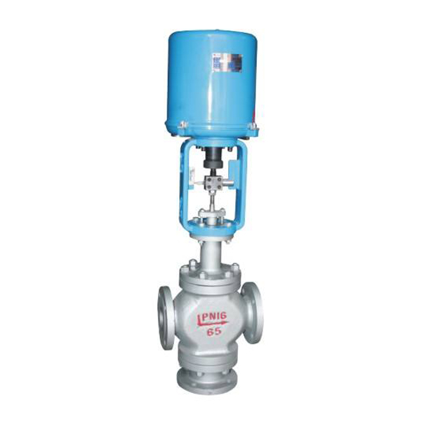
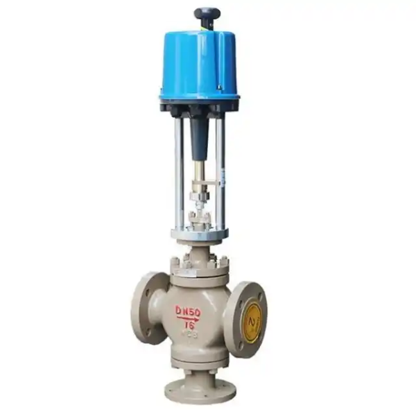
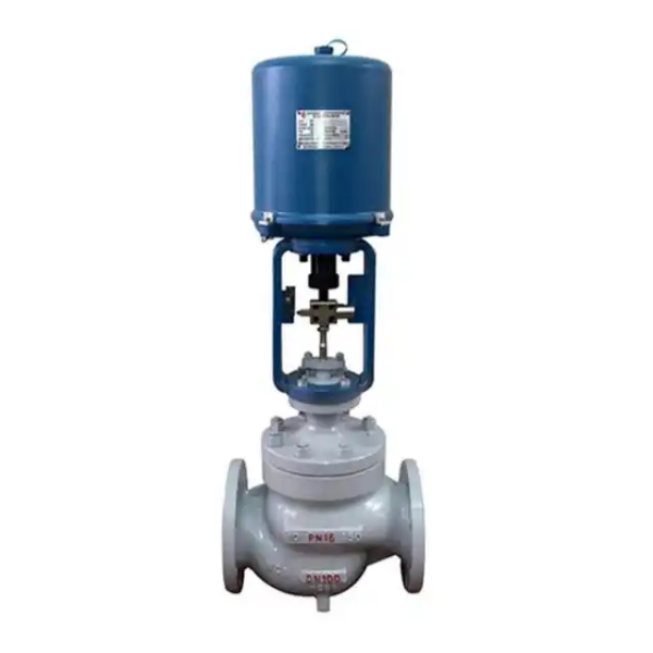
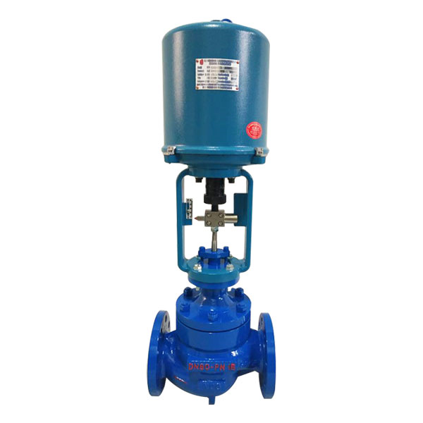
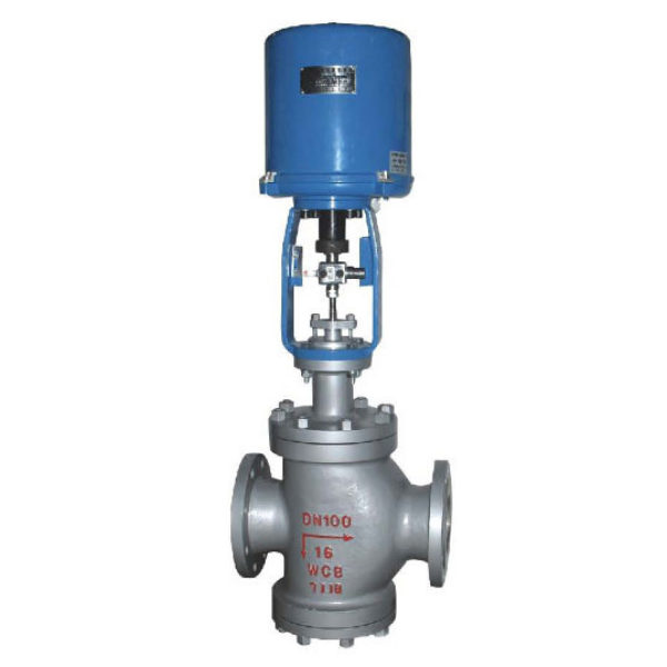
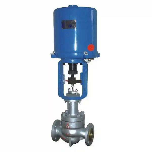
ZDLS electronic electric high-pressure angle control valve consists of a PS series or 3610 series linear-motion electric actuator and a low-flow-resistance angle-type single-seat valve body. The electric actuator is an electronically integrated unit with a built-in servo amplifier. Once the control signal (4-20 mA DC or 1-5 V DC) and power supply are connected, the valve opening can be regulated to adjust process parameters such as pressure, flow rate, liquid level and temperature. It features fast response, simple wiring, large flow capacity, compact size and high regulating accuracy. The angle-type high-pressure control valve was developed to address the serious problems of short service life, easy fracture of the valve stem and easy detachment of the bushing under severe working conditions of high pressure or high differential pressure with serious cavitation and erosion. It employs multi-stage throttling to distribute the differential pressure, reducing cavitation, erosion and turbulence damage, and greatly improving the service life of the control valve. In urea systems in particular, its service life is 2-3 times longer than that of ordinary high-pressure valves. The valve body is of right-angle design with a single-guided plug. The flow path is simple with low resistance, making it especially suitable for regulating high-viscosity fluids and media containing suspended solids and particles, avoiding coking, sticking and clogging.
Control Valve Technical Parameters
|
Nominal Diameter (mm)
|
6
|
10
|
15
|
25
|
|||||||||||||||
|---|---|---|---|---|---|---|---|---|---|---|---|---|---|---|---|---|---|---|---|
| Valve Seat Diameter (mm) | 3 | 4 | 6 | 4 | 5 | 7 | 8 | 10 | 6 | 7 | 8 | 10 | 12 | 7 | 8 | 10 | 12 | 16 | 20 |
| Rated Flow Coefficient Kv | 0.04 | 0.1 | 0.1 | 0.4 | 0.4 | 1 | 1.6 | 2.5 | 4 | 6.3 | 8 | ||||||||
| 0.16 | 0.4 | 0.16 | 1 | 1.6 | 2.5 | 0.63 | 1 | 1.6 | 2.5 | 4 | |||||||||
| 0.063 | 0.25 | 0.25 | 0.63 | ||||||||||||||||
| Nominal Diameter (mm) | 32 | 40 | 50 | 65 | 80 | 100 | 125 | 150 | 200 | ||||||||||
| Valve Seat Diameter (mm) | 16 | 20 | 30 | 20 | 38 | 30 | 50 | 38 | 65 | 50 | 80 | 65 | 100 | 65 | 125 | 100 | 150 | 125 | 200 |
| Rated Flow Coefficient Kv | 6.3 | 8 | 16 | 8 | 25 | 16 | 40 | 25 | 63 | 40 | 100 | 63 | 160 | 100 | 250 | 160 | 400 | 250 | 600 |
| Rangeability | R = 20:1 when Kv < 18; R = 30:1 when Kv > 18 | ||||||||||||||||||
| Nominal Pressure | 1.6, 4.0, 6.4, 10, 16, 22, 32 MPa | ||||||||||||||||||
| Plug Form | Cage-guided single-seat plunger-type plug | ||||||||||||||||||
| Flow Characteristic | Linear | ||||||||||||||||||
| Action | Direct-acting, reverse-acting | ||||||||||||||||||
| Working Temperature (°C) | Normal type: -40 ~ +230; cooling-fin type: +230 ~ +450; special order: +450 ~ +600 | ||||||||||||||||||
| Flange Standard | Per JB/T2769-92; also available per ANSI, JIS, DIN on request | ||||||||||||||||||
| Control Signal | 4-20 mA DC; 1-5 V DC; 0-10 V DC (depending on the actuator fitted) | ||||||||||||||||||
| Power Supply | 220 V AC, 50 Hz; 380 V AC, 50 Hz (depending on the actuator fitted) | ||||||||||||||||||
|
Nominal Diameter (mm)
|
20
|
25
|
40
|
50
|
65
|
80
|
100
|
150
|
200
|
250
|
300
|
|||||
|---|---|---|---|---|---|---|---|---|---|---|---|---|---|---|---|---|
| Valve Seat Diameter (mm) | 10 | 12 | 15 | 20 | 25 | 32 | 40 | 50 | 65 | 80 | 100 | 125 | 150 | 200 | 250 | 300 |
| Rated Flow Coefficient Kv | 1.6 | 2.5 | 4 | 6.3 | 10 | 16 | 25 | 40 | 63 | 100 | 160 | 250 | 400 | 630 | 1000 | 1600 |
| Rangeability | 30:1 | |||||||||||||||
| Nominal Pressure | Standard products: 1.6, 4.0, 6.4 MPa | |||||||||||||||
| Plug Form | Single-seat plunger-type plug | |||||||||||||||
| Flow Characteristic | Linear, equal percentage | |||||||||||||||
| Working Temperature (°C) | Normal type: -40 ~ +230; cooling-fin type: +230 ~ +450; special order: +450 ~ +600 | |||||||||||||||
| Flange Standard | Per JB78-59, JB79-59; also available per JB/79.1-94, JB/79.2-94, ANSI, JIS, DIN on request | |||||||||||||||
Products with working temperature, nominal pressure or nominal diameter beyond the listed range can be supplied on request.
Performance Specifications
Leakage rate: Class IV, less than 10-4 of rated flow capacity.
Hysteresis: 2.0% with 361L actuator; 1.0% with PSL actuator.
Basic error: ±2.5% with 361L actuator; ±1.0% with PSL actuator.
Note: Tests are performed with standard PTFE packing.
Main Parts Materials
Valve body: ZG230-450, ZG1Cr18Ni9Ti, 316, 316L, wear-resistant alloy, etc.
Plug and seat: 1Cr18Ni9Ti, 316, 316L, wear-resistant alloy, F4, etc.
Packing: PTFE, flexible graphite.
Allowable Differential Pressure
|
Nominal Diameter (mm)
|
20
|
25
|
40
|
50
|
65
|
80
|
100
|
150
|
200
|
250
|
300
|
||||||
|---|---|---|---|---|---|---|---|---|---|---|---|---|---|---|---|---|---|
| Valve Seat Diameter (mm) | 10 | 12 | 15 | 20 | 25 | 32 | 40 | 50 | 65 | 80 | 100 | 125 | 150 | 200 | 250 | 300 | |
| Actuator | Allowable Differential Pressure ΔP (MPa) | ||||||||||||||||
| With PSL | PSL202 | 6.4 | 6.4 | 6.4 | 4.90 | 3.14 | 1.92 | 1.23 | 0.78 | ||||||||
| PSL204 | 4.31 | 2.76 | 1.76 | 1.04 | 0.69 | 0.44 | |||||||||||
| PSL208 | 1.86 | 1.23 | 0.78 | 0.50 | 0.35 | 0.20 | |||||||||||
| PSL320 | 1.26 | 0.87 | 0.49 | 0.32 | 0.22 | ||||||||||||
| With 361L | 361LSA-20 | 6.4 | 6.4 | 6.4 | 4.90 | 3.14 | 1.92 | 1.23 | 0.78 | ||||||||
| 361LSB-50 | 4.79 | 3.06 | 1.96 | 1.16 | 0.76 | 0.49 | |||||||||||
| 361LSC-65 | 1.51 | 0.99 | 0.64 | 0.41 | 0.28 | ||||||||||||
| 361LSC-99 | 0.63 | 0.44 | 0.25 | 0.16 | 0.11 | ||||||||||||
Note: (1) The actual configuration must be determined according to specific process parameters. (2) If the allowable differential pressure is unclear or the maximum working differential pressure exceeds the listed range, please contact us and a suitable solution can be provided.
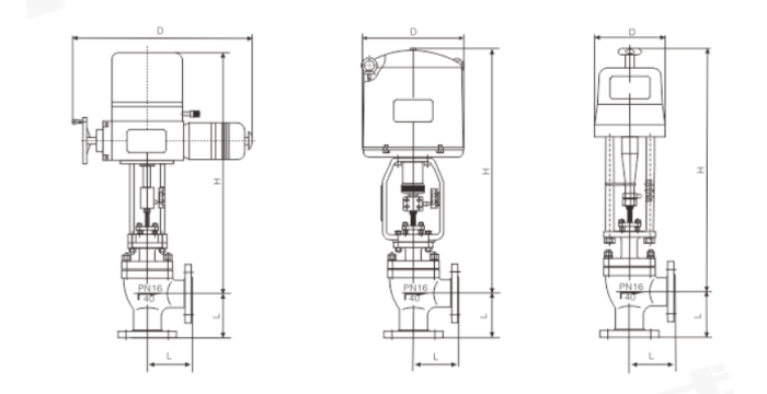
Overall Dimensions
|
Nominal Diameter (mm)
|
20
|
25
|
32
|
40
|
50
|
65
|
80
|
100
|
125
|
150
|
200
|
||
|---|---|---|---|---|---|---|---|---|---|---|---|---|---|
| L1 (mm) | 98 | 105 | 105 | 120 | 135 | 190 | 225 | 270 | 315 | 367 | |||
| L2 (mm) | PN1.6 MPa | 85 | 95 | 115 | 115 | 130 | 145 | 155 | 175 | 200 | 240 | 300 | |
| PN4.0 MPa | 85 | 95 | 115 | 115 | 130 | 145 | 155 | 175 | 200 | 240 | 300 | ||
| PN6.4 MPa | 100 | 115 | 130 | 130 | 150 | 170 | 190 | 215 | 250 | 275 | 325 | ||
| With PSL | H (mm) | Plain | 753 | 761 | 789 | 778 | 793 | 819 | 858 | 893 | 921 | 951 | 956 |
| Cooling-fin | 883 | 891 | 919 | 908 | 923 | 892 | 1021 | 1056 | 1120 | 1150 | 1156 | ||
| D (mm) | 176 | ||||||||||||
| Weight (kg) | 13.5 | 22.5 | 25.5 | 29.5 | 50 | 60 | 78 | 119 | 157 | 255 | |||
| With 361L | H (mm) | Plain | 516 | 542 | 552 | 688 | 744 | 783 | 818 | 976 | 1006 | 1036 | |
| Cooling-fin | 646 | 654 | 682 | 818 | 907 | 946 | 981 | 1175 | 1205 | 1235 | |||
| D (mm) | 225 | 310 | |||||||||||
| Weight (kg) | 21 | 30 | 33 | 41 | 45 | 65 | 75 | 93 | 172 | 210 | 308 | ||


 No products in the cart.